36
7 IN-WELL ASSEMBLY AND
INSTALLATION
SEE REFERENCE SECTION At the end of
this manual (Section 13) you will find instruc-
tions for wellhead assembly, water storage,
control and monitoring of water supply, pipe
sizing, freeze protection, and more.
7.1 Rubber Spacers (Models -07, -10, -14, -20 only)
This applies ONLY to models HR-07, 10, 14
and 20 (HR-07, 14 and 20 pump ends)
Helical rotor pumps vibrate due to the eccen-
tric rotation of the helical rotor. This is normal.
Rubber spacers reduce the vibration that may
be transferred to the well casing. Models –03
and –04 vibrate very slightly so they are not
supplied with rubber spacers.
Clearance for drilled well casings Rubber
spacers fit a 6" (150 mm) inside-diameter or
larger well casing.
Cut the rubber spacer legs to fit smaller
casing If you are installing the pump in a well
casing smaller than 6", cut the spacer legs.
Grooves indicate where to cut for a 4" (100
mm) casing. Use a fine-tooth saw to cut the
rubber.
CAUTION The
threads in the
check valve
require an
adhesive seal-
ant. They are not
tapered pipe
thread. Normally,
there is no reason
to remove the
check valve. If
you do remove it,
use a hardening
adhesive sealant
or epoxy glue
when you replace
it. See CAUTION
in Section 9.1.
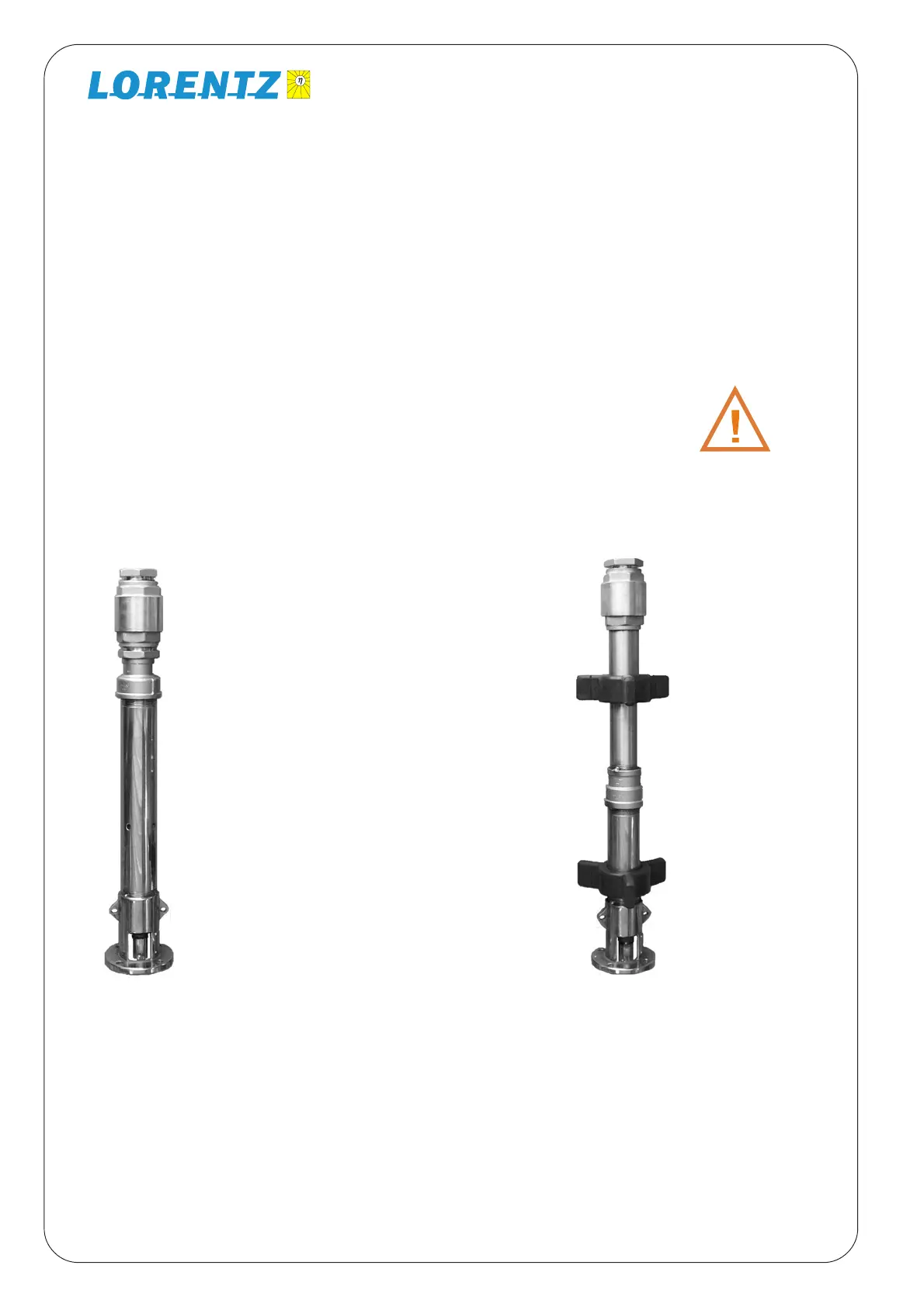
These helical rotor models do
NOT have rubber spacers:
HR-03
HR-04
HR-04H
These models
have rubber
spacers:
(HR-07)
(HR-10)
(HR-14)
(HR-20)