68
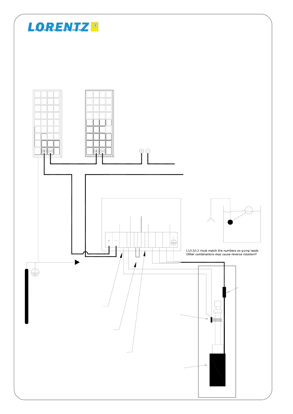
13.11 System Wiring Diagram for Solar-direct (non-battery) System
Power
In
Pump
Ground
Earth
Ground
Red
Black
Yellow
12345
Low-water sensor probe
Low Water
Level Probe
Pump Motor
Submersible
Cable
Splice
For wire size, refer to Sizing Table.
Float Switch
(Optional)
Connect to float
switch terminals.
67
To any ground
terminal at
controller
Connect to bypass
Connect for Battery Mode
L1 L2 L3
If you are not using the
low-water probe, install
a jumper wire between
terminals 1 and 2.
Remote
Float
Switch
NO
com
NC
If you are not using a
float switch, install a
jumper wire between
terminals 4 and 5.
WARNING
TEST max open circuit voltage:
If you are using a
battery system, install a
jumper wire between
terminals 6 and 7.
PV Modules (Solar Panels)
Before connecting the array to the
controller measure the open-
circuit voltage. It must be within a
range of
PS200 : 35-90V DC
PS600 : 75-135V DC
PS1200: 110- 180V DC
PS1800: 110- 180V DC
Float Switch (optional)
Float Switch Kit makes contact on
rise to stop pump.
Connect termins 3 (NO) and 4
(COM) and connect terminals 4
and 5 with jumper wire.
This is an example, using 2-8 X 12V-nominal PV modules. Your system may vary in the
number, voltage, and configuration of PV modules. The system here below is typical for either
a PS200 (2-4 modules in Series) or PS600 (4-6 modules in Series) or PS1200 ( 6-8 modules
in Series) or PS1800 (6-8 modules in series)
PV-Array 2...8 Panels