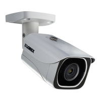
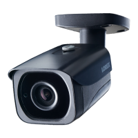
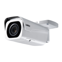
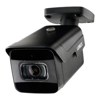
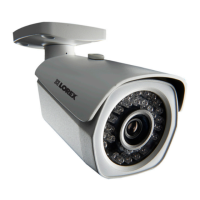
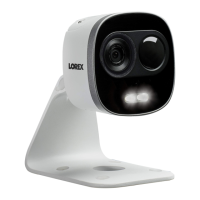
4K IP Active Deterrence
Security Camera
Quick Start Guide
www.lorex.com
Safety Precautions
* Per camera in multi-camera packs
Package Contents
LNB8105X_QSG_EN_R2
Need Help?
Visit us online for up-to-date software and
complete instruction manuals.
Click on the Downloads tab
4
Visit lorex.com
Search for the model number
of your product
Click on your product in the
search results
3
2
1
Installing the Camera
Ceiling mount / table top stand installation:
The camera includes a ceiling mount/table top stand and a wall mount. The ceiling
mount/table top stand may come pre-attached with the camera depending on the
camera configuration. Follow the appropriate installation instructions below:
Copyright © 2018 Lorex Corporation
As our products are subject to continuous improvement, Lorex reserves the right to modify product design,
specifications and prices, without notice and without incurring any obligation. E&OE. All rights reserved.
English Version 2.0
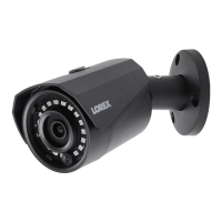
LNB8105X Series
• 4K IP Active Deterrence Security Camera
• Ceiling Mount / Table Top Stand*
• Wall Mount*
ATTENTION:
It is recommended to connect the camera to the NVR or an external PoE switch. If using a DC power adapter (not
included) with the camera, a REGULATED power supply is REQUIRED for use with this camera. Use of a non-
regulated, non-conforming power supply can damage this product and voids the warranty.
• Read this guide carefully and keep it for future reference.
• Follow all instructions for safe use of the product and handle with care.
• Use the camera within given temperature, humidity and voltage levels noted in the camera’s
specifications.
• Do not disassemble the camera.
• Do not point the camera directly towards the sun or a source of intense light.
• Periodic cleaning may be required. Use a damp cloth only. Do not use any harsh, chemical-based
cleaners.
• The supplied cable is rated for surface and in-wall mounting only. Cables for
floor-to-floor installations are sold separately (CMR type). These and other cables are available
at lorex.com.
ATTENTION:
Test your camera prior to selecting a permanent mounting location by temporarily connecting the camera and cable
to your NVR.
For ceiling installation:
1. Remove the pre-inserted silicon plugs (4×) from the base (see
Figure 2).
2. Set the ceiling mount in the desired mounting position and mark
holes for screws and cables through the mounting base (or use
the included mounting template).
NOTE: Adjusting the angle of the camera is limited with this
installation. Ensure you angle the ceiling mount towards the
desired viewing area.
3. Drill holes where marked. If required, insert the included drywall anchors (4×).
4. Mount the ceiling mount to the mounting surface using the provided screws (4×).
Make sure all screws are fastened tightly.
For table top:
NOTES:
• You may choose to use the included wall mount for ceiling installation. Using the wall
mount for ceiling installation will provide more side-to-side angle adjustment but has
limited up/down adjustment. Prior to installation, ensure you test the camera view to
see which installation is the most appropriate based on your desired camera viewing
area. See “Wall mount installation” for more information.
• If the camera comes pre-attached with the ceiling mount/table top stand, detach it
from the camera.
1. With the adjustment ring securely fastened to the
bolt on the table top stand, screw the camera onto
the table top stand (see Figure 5).
NOTE: Skip this step if your camera has the ceiling
mount/table top stand pre-attached.
2. Connect cables as shown in the section “Connecting
the Camera”.
Adjustment
Ring
Adjustment
Knob
Mounting
Base
Dimensions
3.0”
75mm
3.8” / 98mm
4.7”
119mm
2.2”
56mm
Camera with Ceiling Mount / Table Top Stand
Camera with Wall Mount
3.0”
75mm
4.4” / 113mm
3.1”
78mm
Silicon
Plug
Figure 2
Adjustment
Ring
Figure 3
Silicon
Plug
Figure 4
5. With the adjustment ring securely fastened to the
bolt on the ceiling mount, screw the camera onto
the ceiling mount (see Figure 3).
6. Twist the camera onto the ceiling mount until the
camera is level, then tighten the adjustment ring.
7. Angle the camera up-and-down as needed. Remove the
pre-inserted silicon plug on the side of the ceiling mount
and tighten the screw using a Phillips screwdriver. Replace
the silicon plug (see Figure 4).
8. Feed the camera cable through the cable opening on the ceiling mount base and
the mounting surface or run the cables along the wall.
9. Connect cables as shown in the section “Connecting the Camera”.
Before Installing the Camera
• Decide whether to run the cables through the wall (drilling
required) or along the wall.
• (Optional) If you run the cables along the wall, use the
included cable guides with the cable guide screws and
optional drywall anchors as needed (see Figure 1).
Drywall
Anchor
Cable Guide
Screw
Cable Guide
Wall mount installation:
Decide whether to run the cables through the wall (drilling required) or along the wall.
Select one of the installation methods below based on cable run method.
NOTE: If the camera comes pre-attached with the ceiling mount/table top stand,
unscrew the camera from the ceiling mount/table top stand before following the steps
below.
Cable Notch
1. Set the wall mount base in the desired
mounting position and mark holes for
screws through the mounting base (or use
the included mounting template).
2. Drill the holes for the screws. Insert the
included drywall anchors (3×) if you are
mounting the camera onto drywall.
3. Mount the camera to the mounting surface
using the provided screws (3×). Make sure
all screws are fastened tightly.
4. With the adjustment ring securely fastened
to the bolt on the wall mount, screw the
camera onto the wall mount.
1. With the adjustment ring securely
fastened to the bolt on the wall mount,
screw the camera onto the wall mount.
2. Set the wall mount base in the desired
mounting position and mark holes for
screws through the mounting base (or
use the included mounting template).
3. Drill the holes for the screws and a hole
for the cables. Insert the included drywall
anchors (3×) if you are mounting the
camera onto drywall.
4. Connect cables as shown in the section
“Connecting the Camera”.
Running the cables along the wall Running the cables through the wall
5. Connect cables as shown in the section
“Connecting the Camera”.
6. Loosen the adjustment knob on the wall
mount base by turning it counter-clockwise.
Adjust the angle of the camera as needed
(see Figure 7).
7. Tighten the adjustment knob when
finished.
5. Feed the camera
cable through the
cable notch and the
mounting surface
(see Figure 6).
6. Mount the camera to the mounting
surface using the provided screws
(3×). Make sure all screws are fastened
tightly.
7. Loosen the adjustment knob on the
wall mount base by turning it counter-
clockwise. Adjust the angle of the camera
as needed (see Figure 7).
8. Tighten the adjustment knob when
finished.
NOTE: (Optional) Use the included cable guides
as needed to run the cables along the wall.
See “Before Installing the Camera” for more
information.
Figure 1
Figure 5
Figure 6
Figure 7
Using the RJ45 Cable Gland (Optional)
Installation Tips
• Point the camera where there is the least amount of obstructions
(i.e., tree branches).
• Install the camera where vandals cannot easily reach.
• This camera is rated for outdoor use. Installation in a sheltered location is recommended.
• Mounting Kit*
• Ethernet Extension Cable*
Camera Ethernet Connector
O-Ring Rubber Stopper
Barrel End Cap
1. Fit the O-ring around the camera Ethernet connector.
2. Feed the Ethernet extension cable through the end cap and the barrel as shown above.
Connect the cable to the camera Ethernet connector.
3. Twist the barrel securely onto the camera Ethernet connector. The o-ring becomes
compressed when the seal is properly tight.
4. Split the rubber stopper to wrap it around the cable between the barrel and end cap as
shown above. Push the rubber stopper toward the barrel until it is underneath the teeth at
the end of the barrel.
5. Twist the end cap securely onto the barrel. The rubber stopper becomes compressed and
will stick out of the end cap slightly when the seal is properly tight.