I451 I GB D F E 10 16 4257Z010
G
B
11
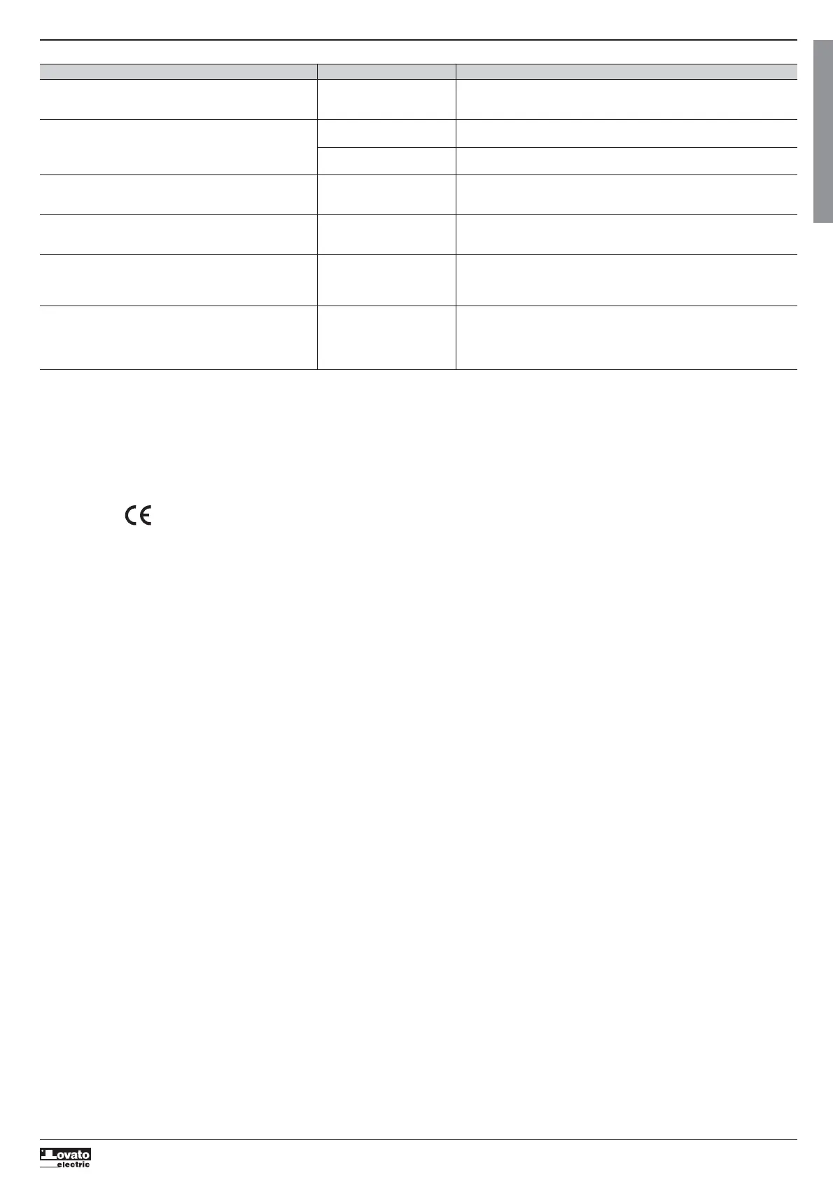
Annex 6: diagnostic table
Symptom Possible causa Recommended action
Once MU is installed, in the first automatic operation, MU has not been installed Disassemble the unit. Change the switch or changeover switch to “0” position.
the unit does not change its position and error led turns ON with switch or changeover Reassemble the unit and repeat the manoeuvre
switch in “0” position
The MU does not operate at all and error led remains OFF Supply voltage out of Check with a multimeter the voltage between terminals 1 and 2 of the MU.
specification The voltage must fulfil the range indicated (see annex 5, page 14)
Wiring to input signals is Check wiring continuity from remote control to the MU
damaged
The MU does not operate according to input signals and neither Power fuse blown Check fuse with a multimeter. If fuse is blown replace it with a new one equal to
padlock slider nor auxiliary manual handle have been used. the specified (see annex 5, page 14)
Error led is ON
After inserting and releasing the auxiliary manual handle the MU Auxiliary manual handle Insert the auxiliary manual handle again and check that that during extraction
does not operate according to input signals. clutch has not returned to it is rejected automatically by the clutch. Check with a multimeter that output between
Error led remains OFF top position terminal 7 and 9 is closed (AUTO mode active)
Using auxiliary manual handle the switch or changeover Auxiliary manual handle Insert the auxiliary manual handle again and check that during extraction
switch position has been changed and after releasing clutch has not returned to it is rejected automatically by the clutch. Check with a multimeter that output between
the handle the MU does not operate according to input signals. top position terminal 7 and 9 is closed (AUTO mode active)
Error LED remains OFF
Using auxiliary manual handle the switch or changeover No coherence in between Insert the auxiliary manual handle again and return the switch or changeover switch
switch position has been changed and after releasing MU position and switch or to prior to failure position. After releasing the handle check that AUTO operation has
the handle the MU does not operate according to input signals. changeover switch position been restablished
Error LED is ON that can not be solved by
MU logical control
NOTE: Once error led is activated, the MU remains locked. MU unlocking is only possible by switching OFF and ON power supply
STANDARDS
– IEC/EN 60947-1 and 3. Low voltage devices. General part and switch - disconnectors.
– IEC/EN/UNE 61000-6, Parts 2 and 4. Electromagnetic compatibility in industrial environments, immunity and emission.
– According to European Standard 2006/95/CE for low voltage.
– According to European standard 2004/108/CE of EMC.
This product in under marking
NOTE: The content of this document can be modified without previous warning.
 Loading...