I451 I GB D F E 10 16 4257Z010
G
B
8
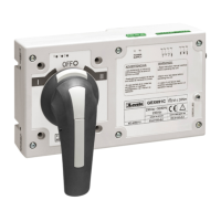
Changeover switch
GE0160E/T4 - GE0200E/T4 + GEX690C
247 30
145
250
83
60
94
GE0201E/T4 - GE0400E/T4 + GEX691C
260 30
216
223
121
310
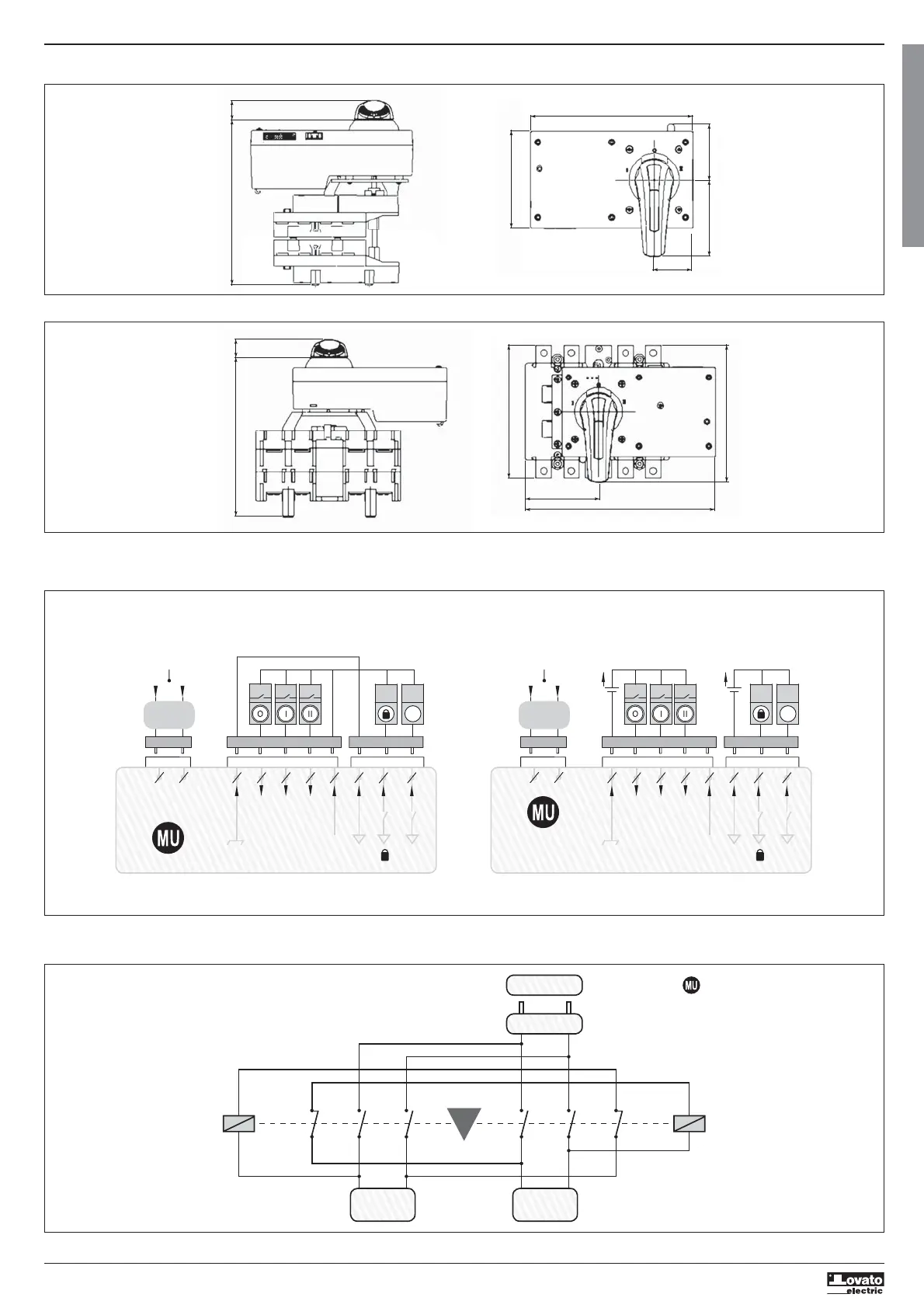
Annex 3:
Wiring diagrams
CHANGEOVER SWITCH I - 0 - II
12 3 75910486
AUT
IN (0) IN (1) IN (2)
230 VAC/DC
+5VDC
GND 1GND 2
OUT OUT
AUT
Go
to 0
Go
to 1
Go
to 2
POWER
SUPPLY
12 3 75910486
AUT
IN (0) IN (1) IN (2)
230 VAC/DC
+5VDC
GND 1GND 2
OUT OUT
AUT
Go
to 0
Go
to 1
Go
to 2
Imax = 120 mA
Vmax = 315 VAC/DC
Imax = 500 mA
Vmax = 40 VAC/DC
POWER
SUPPLY
Wiring proposed for external uninterrupted supply K1, K2 = 230VAC = Coil 230VAC
K1, K2 relays electric and mechanically interlocked
A1
A2
A1
A2
K1 K2
21
21
11 21 31 31 21 11
12 24 34 34 24 12
CONNECTOR
mains
secondary
sources
 Loading...