I451 I GB D F E 10 16 4257Z010
G
B
3
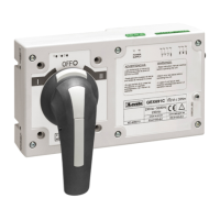
2 - Insert the coupling shaft and fix it with an allen key 2,5 DIN 90011. Without removing the front cover, remove the four screws indicated.
3 - Place the interface and screw it on top of the changeover switch M3.5x30 DIN7985 (x4) screws and A.E.T. 4,3 (x4) washers are included.
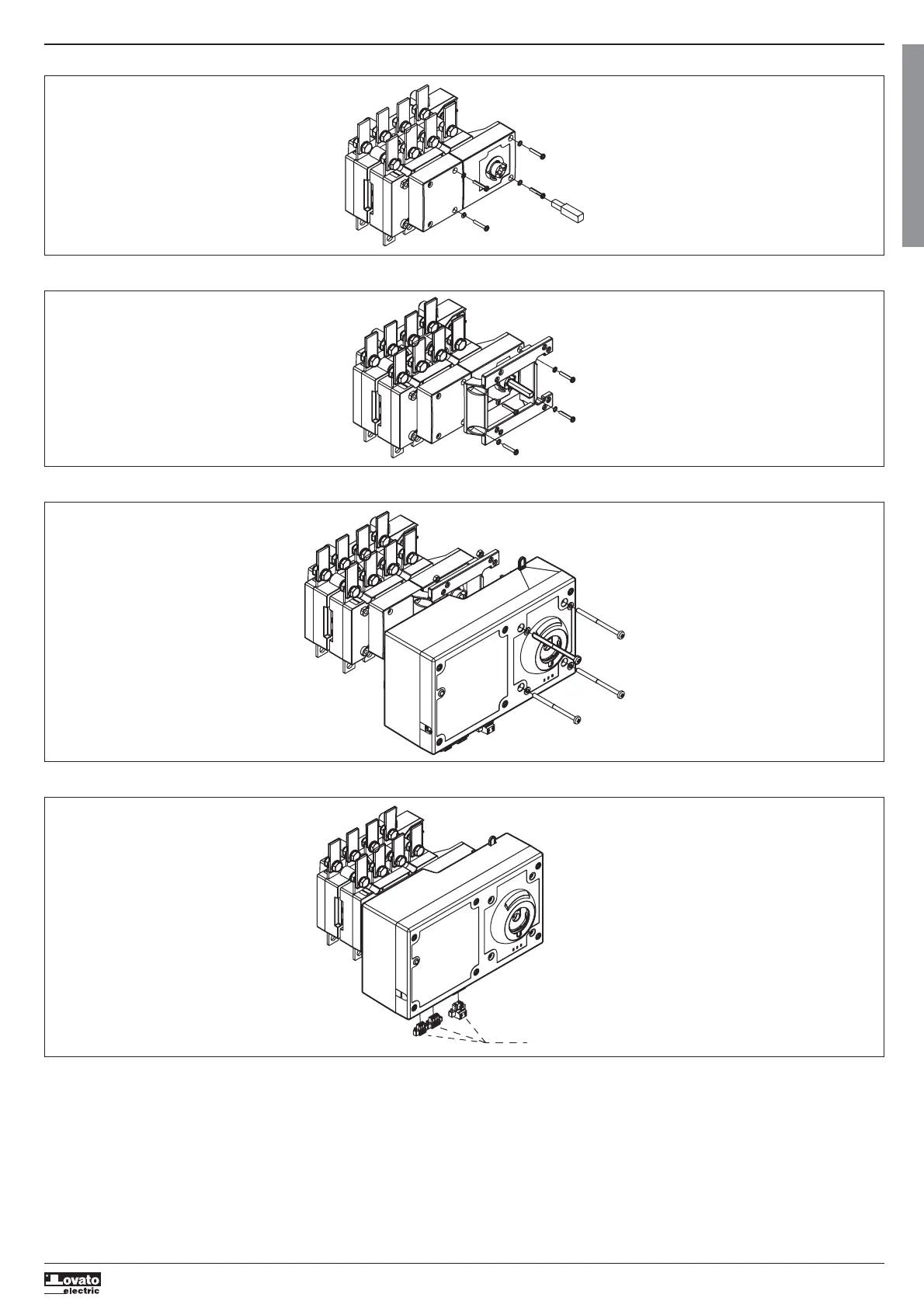
4 - Screw the motorized unit (with changeover switch and MU in 0 (OFF) position). M5 x 75 DIN 7985 (x 4) screws, A.E.T. 5,3 (x 4) washers, M5 DIN 933 (x4) nuts are included.
5 - Locate the connectors (CN1, CN2, CN3) and make the connections according to the electrical diagram (see annex 3, page 8).
CN1, CN2, CN3
 Loading...