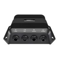
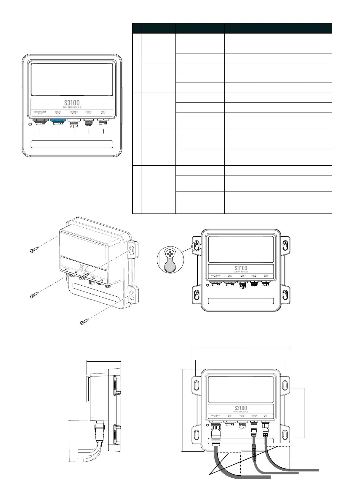
Connectors and LEDs
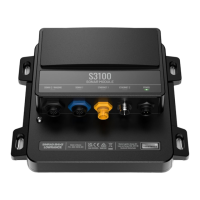
Mounting
Dimensions
A
B
C
D
E
Connector LED Status
A
Sonar 2/
Imaging
(black)
Off Sounder not operating
Flashing - green Searching for bottom signal
On System operating with bottom signal
B
Sonar 1
(blue)
Off Sounder not operating
Flashing - green Searching for bottom signal
On System operating with bottom signal
C
Ethernet 1 Off No connection
On - green Valid connection without data transfer
Flashing - green
and orange
Active connection with data transfer
D
Ethernet 2 Off No connection
On - green Valid connection without data transfer
Flashing - green
and orange
Active connection with data transfer
E Power Off No power
On - dim red Power applied, system is powered off
or overvoltage
On - red System booting
On - green System operating
229.62 mm
9.04 in
192.40 mm
7.57 in
207 mm
8.14 in
115.50 mm
4.54 in
78.80 mm
3.10 in
95.23 mm
3.74 in
Minimum bend radius
70 mm (2.55 in)
 Loading...