ASSEMBLY
OM 0472SB-A [11]
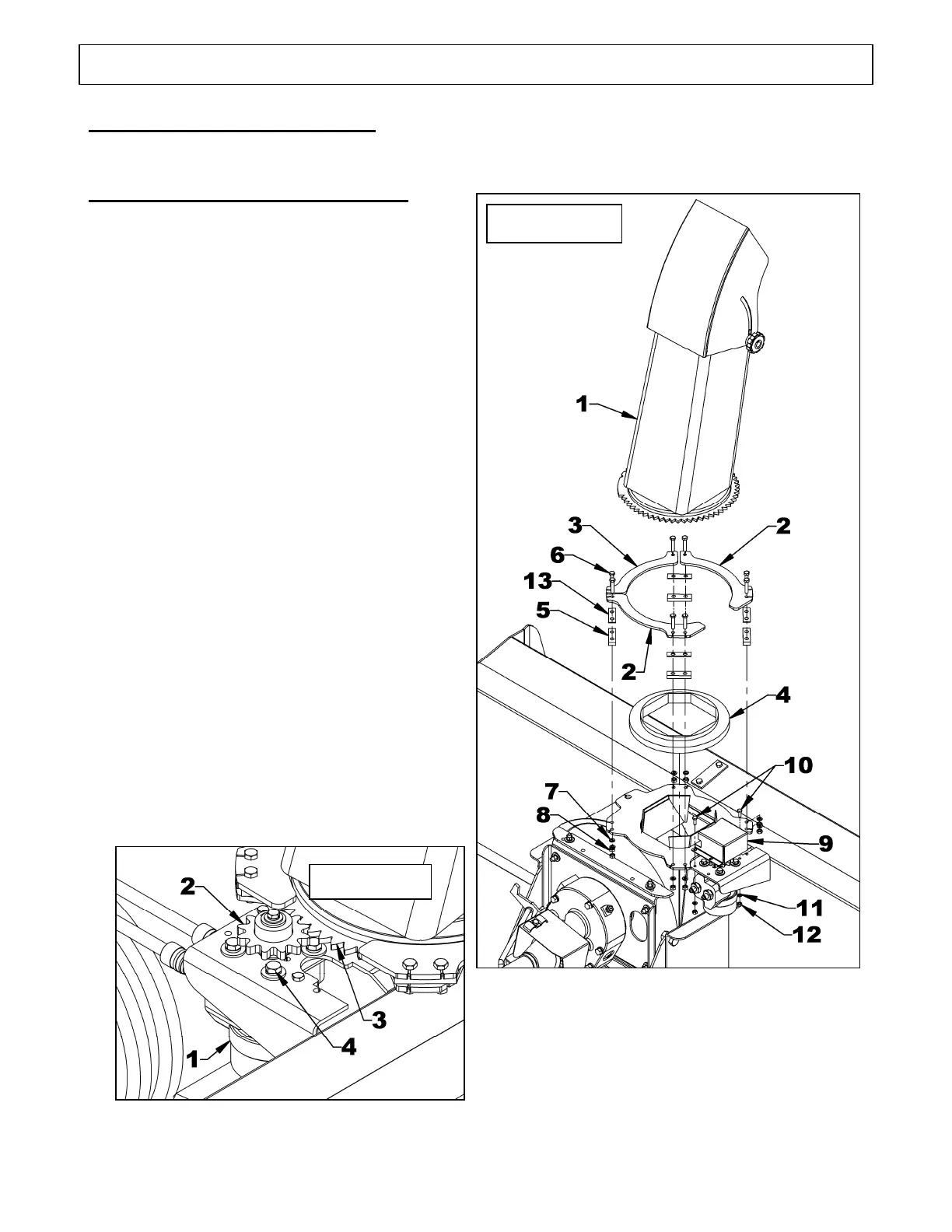
Figure 1
SNOWBLOWER ASSEMBLY
The snowblower is assembled at the factory, however, the chute must be assembled.
Installation of the Chute (Figure 1)
1. Figure 1: Remove the chute (item 1) and
the rotation bushing (item 4) from the crate.
2. Figure 1: Remove the three retaining plates
(items 2-3), the four spacers (item 5), and
the gear guard (item 9) by unscrewing the
ten bolts (items 6-10). Keep the parts close
at hand.
3. Figure 1: Grease the retaining plates
(items 2-3) and the top of the rotation
bushing (item 4) before installing them on
the snowblower.
4. Figure 1: Install the bushing (item 4), then
the chute (item 1), align the eight spacers
(items 5 & 13) with the eight holes on the
housing and secure using the retaining
plates (items 2-3) placing them as
illustrated and the eight 5/16"NC x 1 1/2"
bolts (item 6), lockwashers (item 7) and
nuts (item 8).
5. Figure 1a: Rotate the hydraulic motor
(item 1) so the gear teeth (item 2) connect
as much as possible with the gear teeth of
the chute (item 3). Tighten the bolts
(item 4) at 10 ft-lb (13 N-M).
6. Figure 1: Place the gear guard (item 9) on
top of gear; lock in place with two 1/4" NC
X 3/4" bolts (item 10), lockwashers
(item 11) and nuts (item 12).
Figure 1a
 Loading...