INSTALLATION 5
2.1 Line of Sight
Ideally there should be a clear and direct line of
sight between each sensor and the LSI Gateway
at all possible positions of any mobile structures on
which the system is installed. In ideal conditions
the radio range is about 1300 m (over 4000 ft.).
Typically each wall or window the signal must pass
through reduces the range by half. Metal structures
will attenuate the signal; care should be taken not to
hide the LSI Gateway behind metal plates. A clear
signal between a sensor and the LSI Gateway
improves communication and increases sensor
battery life.
2.2 Antenna Position
For optimal performance communicating antennas
should be parallel to each other without pointing to,
or away from, each other at all possible positions of
any moving structures on which they are installed.
The antenna should have 5 in. of clear space all
around it.
2.3 LSI Gateway Power Supply
If the USB port is in use, the LSI Gateway will
take its power supply from the USB connector.
Otherwise, power should be supplied based on the
following wire colors:
2.3a Wiring
Table: Wire description
Wire Color Description
Red.........................Power supply, 10 to 30 volts
Black ....................................................... Ground
Green .......................................................CAN-H
White ........................................................ CAN-L
Blue or Brown ................................ CAN-Ground
2. INSTALLATION
IMPORTANT! Do not power wash the LSI
Gateway. Power washing the LSI Gateway
voids warranty coverage.
!
WARNING! The system must be installed
in compliance with LSI instructions and
using LSI supplied components only. Failure
to install all parts, or replacing parts or
components with parts or components not
supplied by LSI, may lead to system failure,
serious injury or death.
!
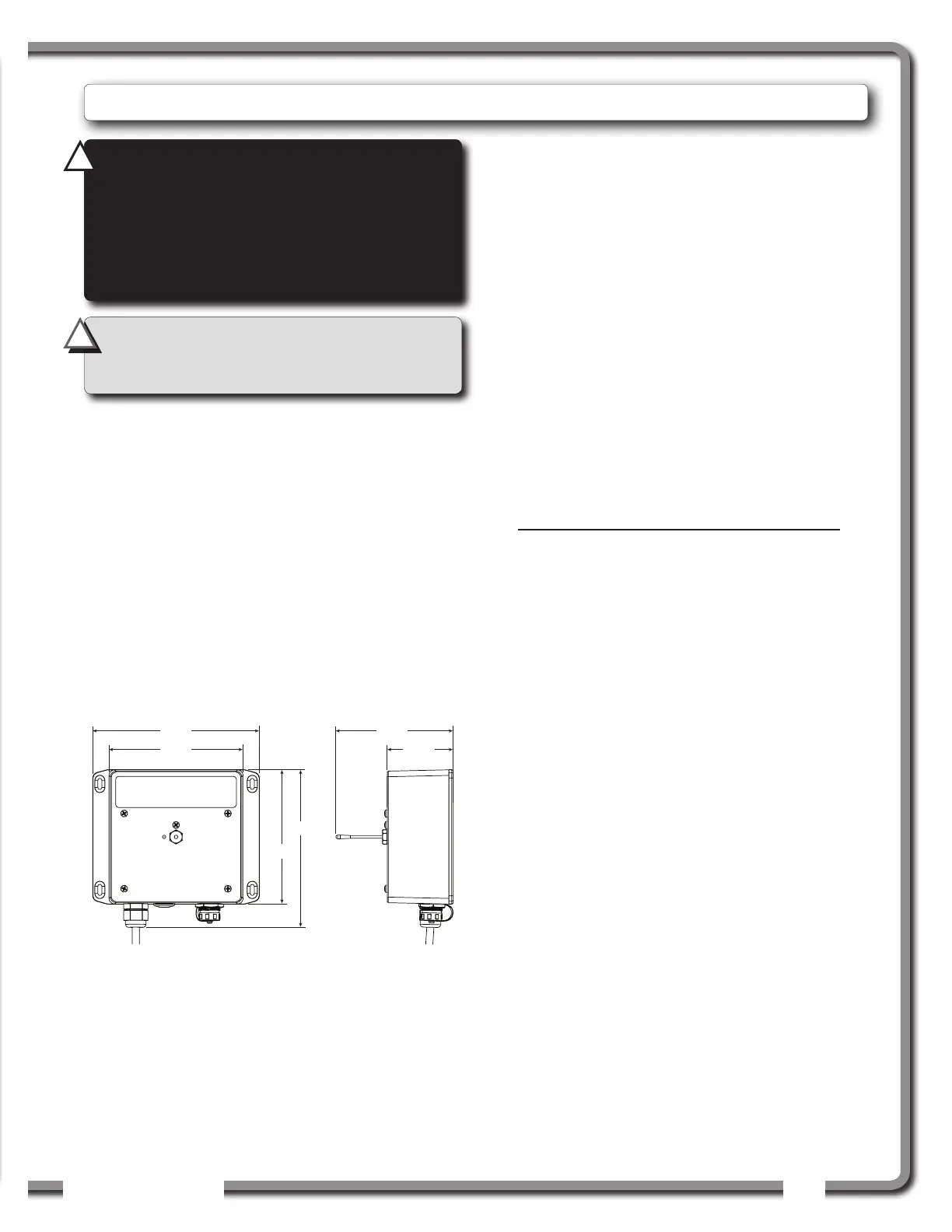
5.44
2.33
5.85
4.72
5.57
4.73
Figure: GS22X-XX LSI Gateway dimensions. Not to scale.
Dimensions are in inches.
 Loading...