LSI Corporation
- 6 -
LSI SAS 9201-16i PCI Express to 6Gb/s SAS HBA User Guide
August 2011
LSI SAS 9201-16i HBA Characteristics
5.2 Connectors
This section describes the different connectors on the LSI SAS 9201-16i HBA. See Figure1 for connector locations.
PCIe Connector (EC1). The LSI SAS 9201-16i HBA supports a x8 interface. The PCIe connection is through the edge
connector, EC1, which provides connections on both the top (EC1B) and bottom (EC1A) of the board. The signal
definitions and pin numbers conform to the PCIe specification.
SAS Connectors (J6, J7, J8, and J9). The LSI SAS 9201-16i HBA supports SAS connections through four SFF-8087
mini-SAS, internal, right-angle connectors.
Activity LED Header (J4 and J5). The LSI SAS 9201-16i HBA has two 4-pin, right-angle, 0.1-in. pitch headers for
driving external activity LEDs. The LEDs on header J4 correspond to activity on Port C and Port D. Header J5
corresponds to activity on Port A and Port B.
UART Connector (J1). The UART connector debug port requires a special cable and LSI support to gather detailed
Input/Output Controller (IOC) status.
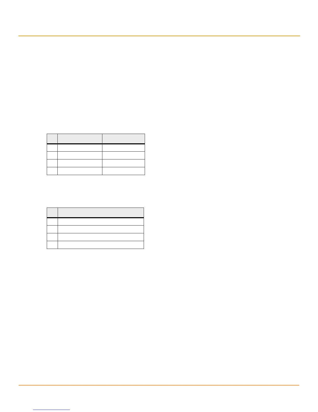
Table 3 LSI SAS 9201-16i LED Header Pinout
Pin J4 Header Function J5 Header Function
1 3.3 V 3.3 V
2 Port C Port A
3Port D Port B
4 3.3 V 3.3 V
Table 4 LSI SAS 9201-16i UART Pinout
Pin Function
1UART_TX
2Gnd
3UART_RX
43.3 V
 Loading...