Whitehaven Fan Installation Instructions
6 | P a g e
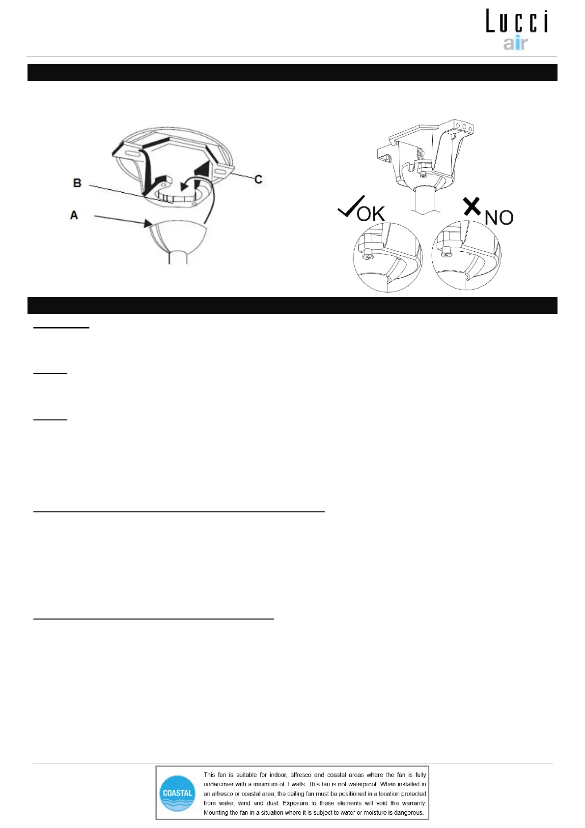
HANGING THE FAN
Lift the fan assembly onto the mounting bracket. Ensure the key slot (A) of the hanger ball is positioned
on the key pin (B) of the mounting bracket (C) to prevent the fan from rotating when in operation. (Fig.8)
ELECTRICAL WIRING DIAGRAM
WARNING: FOR YOUR SAFETY ALL ELECTRICAL CONNECTIONS MUST BE UNDERTAKEN BY A
LICENSED ELECTRICIAN.
NOTE: AN ADDITIONAL ALL POLE DISCONNECTION SWITCH MUST BE INCLUDED IN THE FIXED
WIRING.
NOTE: IF THERE ARE TWO OR MORE DC CEILING FANS INSTALLED IN THE ONE LOCATION, AN
SINGLE-POLE SWITCH IS REQUIRED FOR EACH CEILING FAN. THIS IS REQUIRED WHEN
PROGRAMMING THE REMOTE AND RECEIVER TO PAIR TOGETHER.
Ensure the motor earth wire is connected to the single earthing terminal block “1” in Fig. 9
From mains supply to mounting bracket terminal block: (Fig. 9)
• Connect the live supply wire to the “L” terminal of the terminal block on the mounting bracket.
• Connect the neutral supply wire to “N” terminal of the terminal block on the mounting bracket.
• Connect earth wire to the earth terminal of the terminal block on the mounting bracket.
Hang the fan (Refer to “hanging the fan” Fig. 8).
From mounting bracket to receiver and motor : (Fig. 9)
• Connect the motor earth wire to the single earthing terminal block “1” in the diagram below. (Fig. 9)
• Connect the supply wiring from the mounting bracket to the input of the DC motor driver/receiver.
• Connect the output wires of DC motor driver/receiver to the input wires of the fan motor via 4-port quick
connectors.
• If the fan is with light, Connect the light output wire of the DC motor driver to the input wire of the light kit
via 2-port quick connectors (Fig.9a)