Operating Manual Compact Weather Station
G. Lufft Mess- und Regeltechnik GmbH, Fellbach, Germany 23
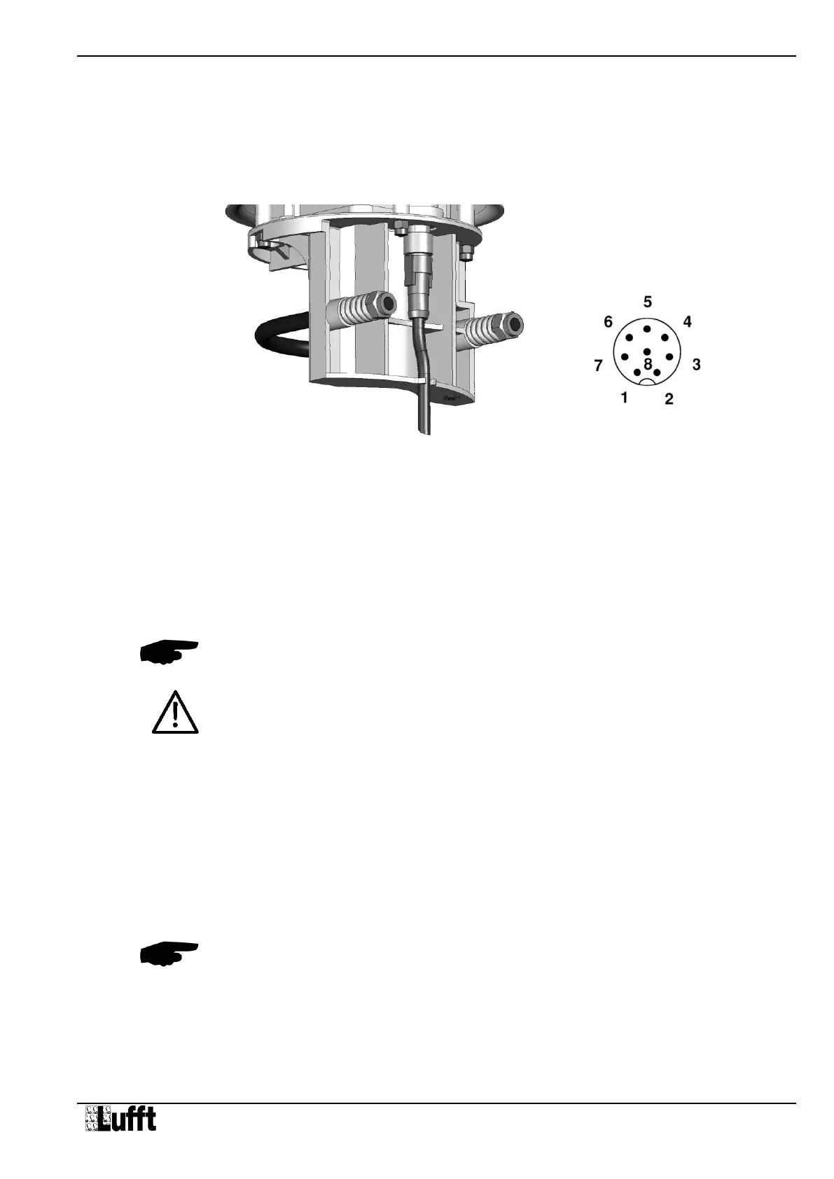
Figure 6: Connections
8 Connections
There is an 8 pole screw connector on the underside of the equipment. This serves to
connect the supply voltage and interfaces by way of the supplied connection cable.
Equipment connector:
View on sensor connection
Pin assignment:
1 White Supply voltage ground
2 Brown Positive supply voltage
3 Green RS485_A / SDI-12 GND
4 Yellow RS485_B / SDI-12 Data Line
5 Gray Jumper for activation of SDI-12 mode
6 Pink Jumper for activation of SDI-12 mode
7 Blue Heating voltage ground
8 Red Positive heating voltage
The cable marking is in accordance with DIN 47100.
Note: The yellow protective cap must be removed before plugging in the equipment.
If the equipment is not connected correctly
- It may not function
- It may be permanently damaged
- The possibility of an electrical shock may exist
When connecting the heating voltage the correct polarity must be strictly observed.
Wrong polarity of the heating voltage, as well as wrong polarity of the supply voltage
will cause damage of the instrument.
8.1 Supply Voltage
The supply voltage for the compact weather station is 12 - 24V DC. The power supply unit
used must be approved for operation with equipment of protection class III (SELV).
8.1.1 Limitations in 12V mode
If the heating is operated on 12V DC, account must be taken of the functional restrictions in
winter operation.
Note: A heating voltage of 24V DC is recommended to guarantee full heating duty.
8.2 RS485 Interface
The equipment has an electrically isolated, half-duplex, 2 wire RS485 interface for
configuration, measurement polling and the firmware update.
See page 35 for technical details.