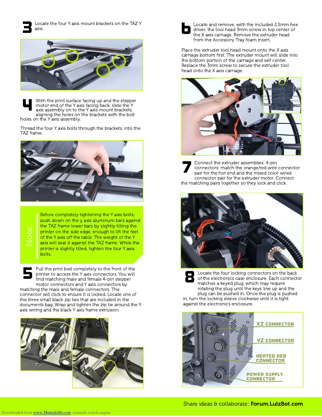
Locate and remove, with the included 2.5mm hex
driver, the tool head 3mm screw in top center of
the X axis carriage. Remove the extruder head
from the Accessory Tray foam insert.
Place the extruder tool head mount onto the X axis
carriage bottom first. The extruder mount will slide into
the bottom portion of the carriage and self center.
Replace the 3mm screw to secure the extruder tool
head onto the X axis carriage.
3
Locate the four Y axis mount brackets on the TAZ Y
axis.
Share ideas & collaborate:
Forum.LulzBot.com
Before completely tightening the Y axis bolts,
push down on the y axis aluminum bars against
the TAZ frame lower bars by slightly tilting the
printer on the side edge, enough to lift the feet
of the Y axis off the table. The weight of the Y
axis will seat it against the TAZ frame. While the
printer is slightly tilted, tighten the four Y axis
bolts.
Note:
Pull the print bed completely to the front of the
printer to access the Y axis connectors. You will
find matching male and female 4-pin stepper
motor connectors and Y axis connectors by
matching the male and female connectors. The
connector will click to ensure it is locked. Locate one of
the three small black zip ties that are included in the
documents bag. Wrap and tighten the zip tie around the Y
axis wiring and the black Y axis frame extrusion.
5
6
Connect the extruder assemblies' 4-pin
connectors: match the orange/red wire connector
pair for the hot end and the mixed color wired
connector pair for the extruder motor. Connect
the matching pairs together so they lock and click.
7
Locate the four locking connectors on the back
of the electronics case enclosure. Each connector
matches a keyed plug, which may require
rotating the plug until the keys line up and the
plug can be pushed in. Once the plug is pushed
in, turn the locking sleeve clockwise until it is tight
against the electronics enclosure.
8
With the print surface facing up and the stepper
motor end of the Y axis facing back, slide the Y
axis assembly on to the Y axis mount brackets,
aligning the holes on the brackets with the bolt
holes on the Y axis assembly.
Thread the four Y axis bolts through the brackets, into the
TAZ frame.
4
 Loading...