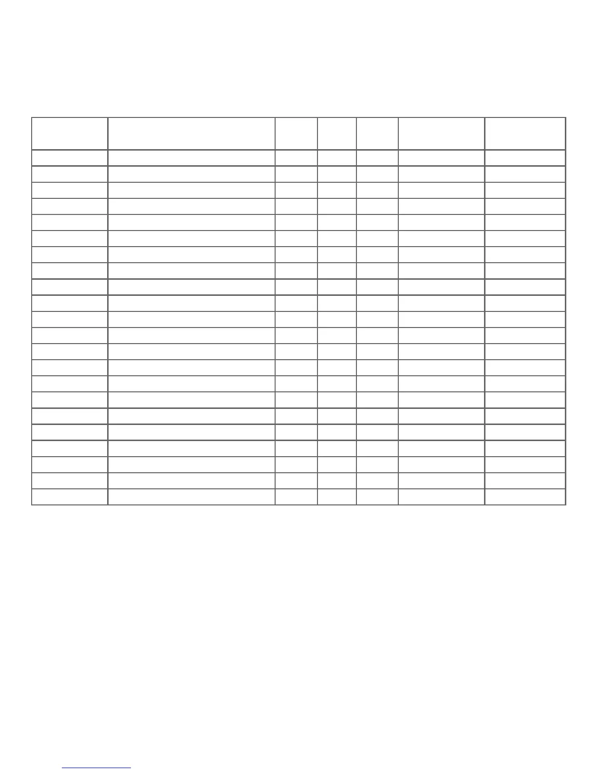
TABLE 8: Continued...
Parameter
No.
Parameter
3P
4W
3P
3W
1P
2W
Trip Point
Set Range
100%
Value
38
39
40
41
43
44
45
46
47
48
49
50
51
52
53
54
101
102
103
113
114
115
Wh Export
VAr Capacitive
VAr Inductive
VA
Watt Demand Imp.*
Watt Max Demand Imp.*
Watt Demand Exp.*
Watt Demand Max Exp.*
VAr Demand Cap.*
VAr Max Demand Cap.*
VAr Demand Ind.*
VAr Demand Max Ind.*
VA Demand*
VA Max Demand*
Current Demand*
Current Max Demand*
VL1-L2
VL2-L3
VL3-L1
I Neutral
Relay Manual OFF
Relay Manual ON
-
-
-
-
Nom
(3)
Nom
(3)
Nom
(3)
Nom
(3)
Nom
(3)
Nom
(3)
(3)
Nom
(3)
Nom
Nom
(3)
Nom
(3)
Inom
Inom
Vnom (L-L)
Vnom (L-L)
Vnom (L-L)
Inom
-
-
10 - 9999999
10 - 9999999
10 - 9999999
10 - 9999999
10 - 120 %
10 - 120 %
10 - 120 %
10 - 120 %
10 - 120 %
10 - 120 %
10 - 120 %
10 - 120 %
10 - 120 %
10 - 120 %
10 - 120 %
10 - 120 %
10 - 120 %
10 - 120 %
10 - 120 %
10 - 120 %
1
1
ü ü ü
ü ü ü
ü ü ü
ü ü ü
ü ü ü
ü ü ü
ü ü ü
ü ü ü
ü ü ü
ü ü ü
ü
ü
ü
ű ű
ű
ű
ű ű
ü ü ü
ü ü ü
ü ü ü
ü ü ü
ü ü ü
ü ü ü
ü
ű ű
ü
ü
ü ü
üü
Note : Parameters 1,2,3 are L-N Voltage for 3P 4W & L-L Voltage for 3P 3W.
*Note : Parameters marked are not applicable for the Lower Model.
(1) For Frequency 0% corresponds to 45 Hz and 100% corresponds to 66 Hz.
(2) For 3P 4W and 1P2W the nominal value is VLN and that for 3P 3W is VLL.
(3) Nominal Value for power is calculated from Nominal Voltage and current values.
(4) Nominal Value is to be considered with set CT/ PT Primary values.
(5) For single phase L1 Phase values are to be considered as System values.
34
 Loading...