5
BASICS
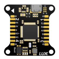
Hardware Setup
Make sure to select your RX input and logic level by bridging the appropriate jumpers.
• Bridge only 3v for SPEKTRUM satellite.
• Bridge only 5v for Futaba, FRSKY S.BUS, ORANGE, etc. (no signal inverter needed).
• Select PPM for PPM, or SRX for Serial RX.
• The 3v jumper only changes voltage output for RX (pin #
6
remains 5v).
Connect ESC signal wires
• Connect the corresponding ESC signal wires to pins labeled
2
in the picture on page 2.
• Ground wires can be connected to the pins labeled
1.
Connect RX
• Connect PPM/SRX, 3.3-5V, GND to pins labeled
3.
Enable Telemetry
• Connect RX port on Receiver to selected TX pin on one of the
USART
pins labeled
5, 7, 8.
Enable feature in CLI:
feature TELEMETRY
In the
Ports
tab in Cleanflight, select the
Telemetry
dropdown to output data on selected
USART.
Connect Buzzer
• Connect buzzer +/- to pins labeled
4
.
Connect Blackbox Device
OpenLog serial data loggers work over simple serial connections and support microSD cards up to
64GB. Your
LUX
flight controller has
3
separate hardware serial (
UART
) TX/RX pin pairs.
• Connect VCC/TX/RX/GND to corresponding pins labeled
5, 6, 7, 8
.
Enable feature in CLI:
feature BLACKBOX
set blackbox_device = 0
In the
Ports
tab in Cleanflight, select the checkbox to enable Blackbox on the
UART
you choose. It
is recommended
not
to connect a wire from
TX
pin on OpenLog logger to
RX
pin on
LUX
.