2|Page
REMOTE ALARM MODULE
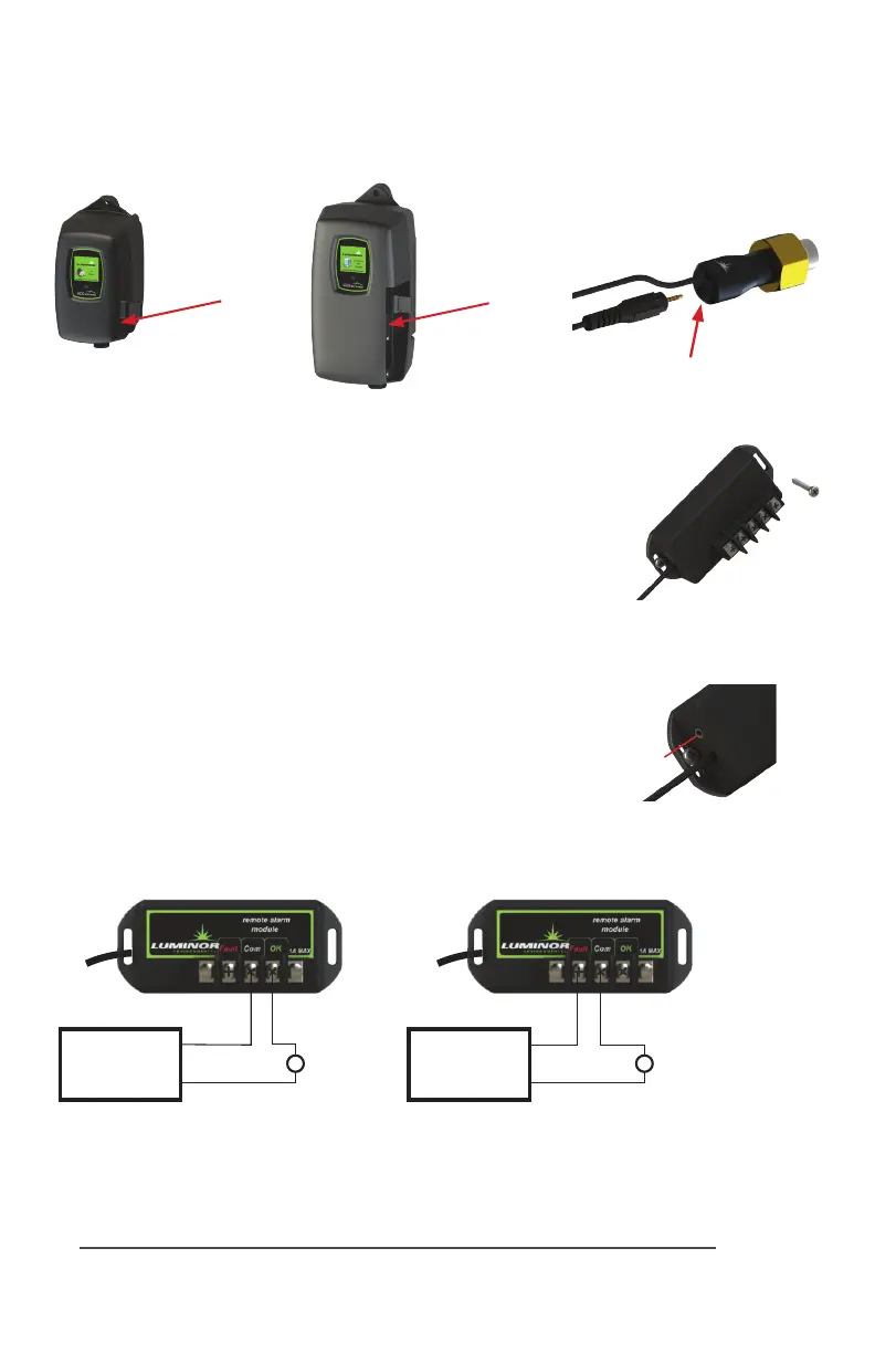
MODEL # MOD-RAM
TheRemoteAlarmmodulecomeswithbothamaleandfemale
IEPconnecon(InniteExpandabilityPort).Toiniatethemodule
simplyplugthemaleplugintotheIEPontheStandardorHigh
Outputcontroller,orintoanyotherBLACKCOMBmodulethat
containsanIEP(sensor,4-20mAmodule,solenoidmodule,etc.)
and then restart the system.
TheRemoteAlarmmoduleisapairofdrycontactsandcanbe
usedtoconnectthecontrollertoaPLCbasedsystem,analarm
buzzer(orlight),oran“OK”light.Maximumcontactrangis30V
/1A.Iftheconnecteddevice(eg.lightorbuzzer)exceedsthe1A
currentrangthenusetheRemoteAlarmModuletocontrolan
appropriatelyratedrelay.
TheremotealarmmodulemustonlybesuppliedatSELV.
Disconnectpowersupplybeforeservicing.
“OK”
Light
Customer
Power Supply
Maximum 30V
“FAIL” Light/Buzzer
Autodialer
Customer
Power Supply
Maximum 30V
Sensor IEP
Installaon
IEP
connecon
BLACKCOMB
Controller
BLACKCOMB-HO
Controller
IEP
connecon
IEP
connecon
Figure 1
Secure module to
wall with screws
Figure 2
IEPconnecon
IEP