4|Page
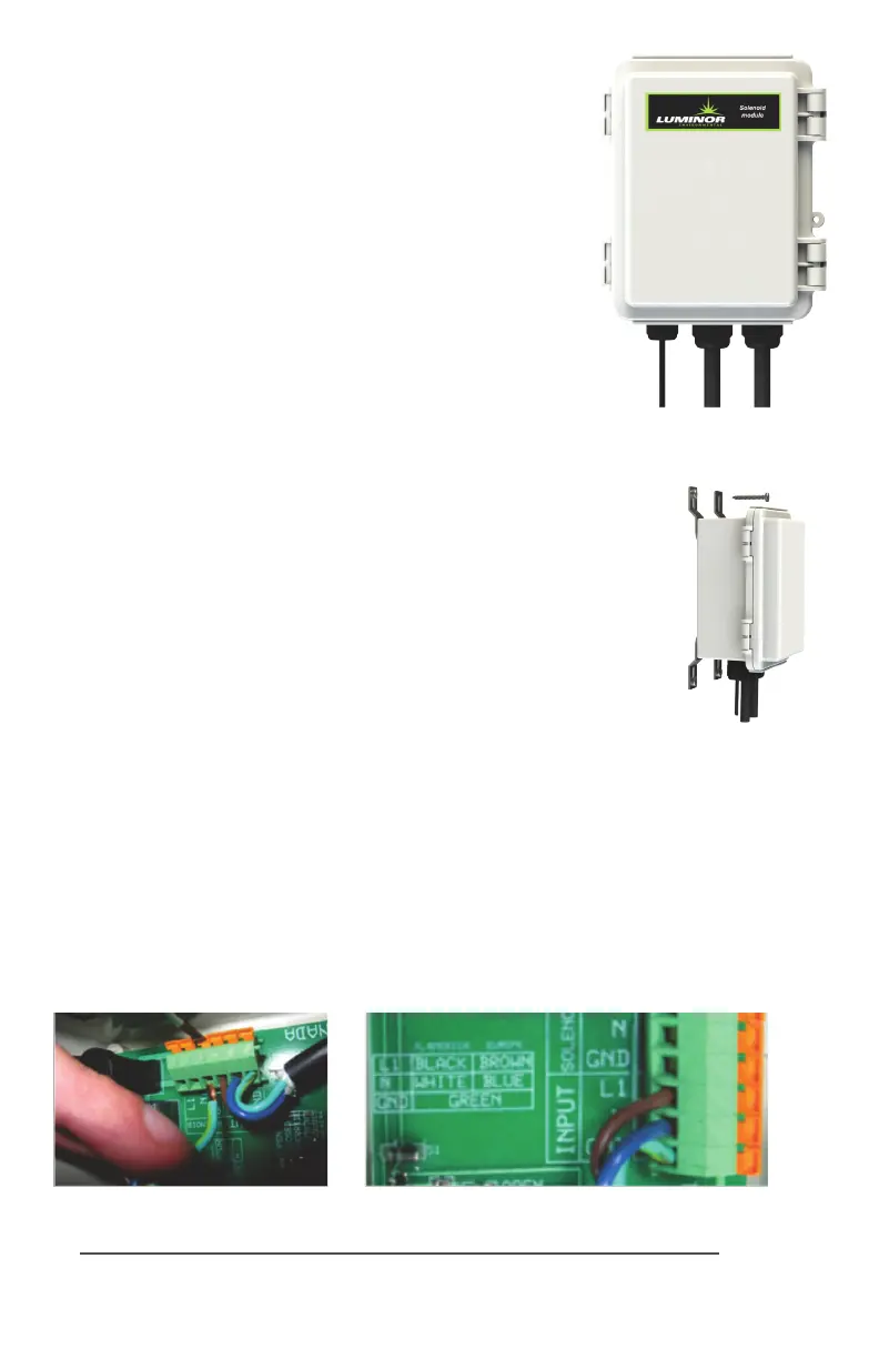
SOLENOID MODULE
MODEL # MOD-SOL1 (in 110V, NEMA 5-15 plug)
MOD-SOL2 (in 230V, CEE 7/7 plug)
MOD-SOL3 (in 230V, BS 1363 plug)
MOD-SOL4 (in 230V, AS/NZS 3112 plug)
TheSolenoidModuleisdesignedtoconnectaNORMALLY
CLOSEDlinevoltagesolenoidvalvetothecontroller.Itis
possibletousea12Vor24Vnormallyclosedsolenoidby
replacingtheACpowercord.Notethatthemaximumcontact
rangis240VAC(50-60Hz)/30VDC/2A.
LOCATION
Step 1) Findasuitablelocaononthewallforthesolenoid
module. The module must be installed close enough to the
controller,ortheUVsensortobeabletopluginthemale
IEP connector. The module must also be installed close
enough to the actual solenoid valve and this distance will
bedependentonthecordlengthoftheparcularsolenoid
valve that is used.
Step 2)Pickalocaonforthesolenoidvalveandinstallas
perthemanufacturer’sdirecons.Thesolenoidmodule
requiresbareleadsforconnecontoterminalblocks,so
ifthesolenoidcablehasaplugaached,removetheplug
andstripthewirestoasuitablelength.
INSTALLATION
Step 1) MakesurethesolenoidvalvecableisNOTpluggedintotheelectricaloutlet.Insert
thesolenoidvalvecablethroughthecenterholeofthemiddlestrainrelief.Connectthethree
electricalwirestotheterminalblockthatismarked“SOLENOID”(seeFig.2).Connectthe
groundwireintheposionmarked“GND”,thelinevoltagewireintheposionmarked“L1”
andtheneutralwireintheposionmarked“N”.Typicalwirecolourconguraonsaremarked
directlyonthecircuitboardtotheleoftheSOLENOIDterminalblocktoaidinthisprocess
(seeFig.3)Ifyouareunsureofthecorrectwiringconguraonforyouparcularsolenoid
valve,pleasecontactanapprovedelectricalcontractor.Onceallthelinevoltageconnecons
havebeenmade,ghtenthestrainreliefnuttosecurethecabletothesolenoidmodule.
Figure 3
WiringColourGuide
Figure 2
SolenoidWireInstallaon
Figure 1
Secure
module to
wall with
screws
 Loading...