39
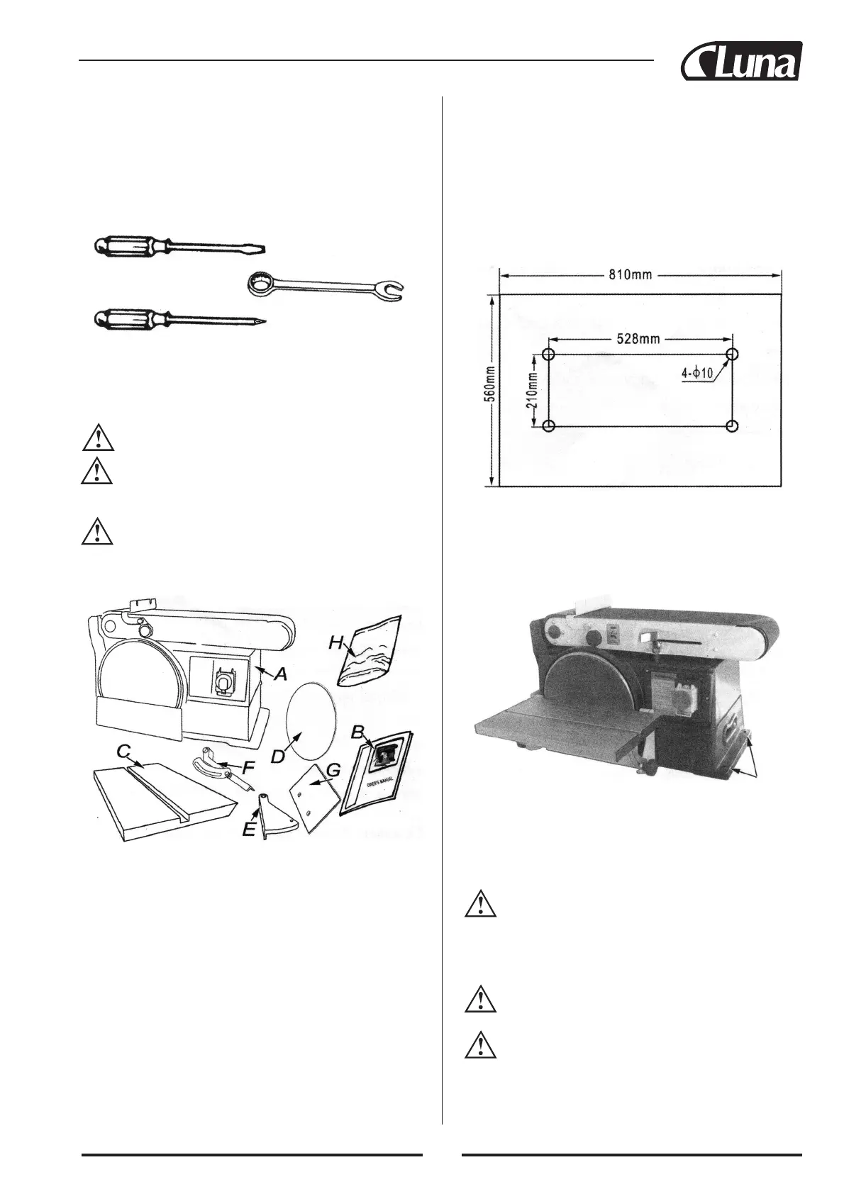
PHILLIPS TYPE SCEWDRIVER
STAND
ARD SCREWDRIVER
10 mm WRENCH
Dress for
safety.
Any power sander can throw foreign objects into the eyes. This
can cause permanent eye damage.
Wear safety goggles. Do not
wear loose clothing, gloves, neckties or jewelry (rings, wrist wat-
ches). They can get caught and draw you into moving parts.
UNPACKING
AND CHECK CONTENTS
Tools need:
This machine is shipped complete in one carton. Separate all parts
from packing materials and check each item with illustration and
“bag of loosen parts”.
NOTE: Make certain all items are accounted for
, before
discarding any packing material.
W
ARNING! To avoid injury, if any parts are missing, do
not attempt to assemble the Belt and Disc sander, unplug in
the power cord, or turn the switch on until the missing parts are
obtained and installed correctly.
WARNING! For your own safety, never connect plug to
power source outlet, or switch on until all assembly steps
are complete and until you have read and understood the entire
Owner’s manual.
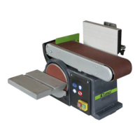
Mounting holes
ITEM DESCRIPTION QTY
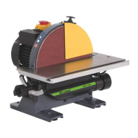
A Belt & Disc Sander Assembly 1
B Owner’s Manual 1
C Table
1
D Sanding Disc 1
E
Mount, Support Table 2
F Table Support W/Scale 2
G Work Table for Belt 1
H Bag of Loosen Parts 1
Contain:
Hex “L” Wrench 3 mm 1
Hex “L” Wrench 6 mm 1
Sunk head screw M6x16 2
Pan head screw M6x16 4
Hex nut M6 4
External lock washer 6 mm 8
Wing nut 6 mm 2
Flat washer 6 mm 2
2. Locate and mark the holes through workbench.
3. Drill 4-10 mm diameter holes through workbench.
4.
Place belt and disc sander on workbench aligning holes on base
with holes drilled in workbench.
5. Insert 4 M8 screws and tighten hex nuts.
ASSEMBLY
Mounting Belt and Disc Sander to
Workbench
If belt and disc sander is to be used in a permanent location, it
should be fastened securely to a firm supporting surface such as
workbench. If mounting to a workbench, holes should be drilled
through supporting surface of the workbench using dimensions
illustrated.
1.
The unit should be bolted securely using M8 screws and hex
nuts (not included). screw lenght should be 50 mm plus the
thickness of bench top.
An alternate method of mounting is to fasten belt and disc sander
to a mounting board. The board should be of suf
ficient size to
avoid tipping of sander while in use. Any good grade of plywood
or chipboard with 19 mm minimum thickness is recommended.
(Thinner chipboard can break.)
CAUTION! To avoid injury from tool movement use M8
or large screws and nuts. Follow instructions for mounting
and using M8 flat head screws, lock-washers, and hex nuts (not
included). Screw length should be 50 mm plus the thickness of the
mounting board.
NOTE: For proper stability, holes must be counter sunk so
screw heads are flush with the bottom surface of supporting
board.
WARNING! To avoid injury from tool movement, suppor-
ting surface where belt and disc sander is mounted should
be examined carefully after mounting to insure that no movement
during use can result. If any tipping or walking in noted, secure
workbench or support or supporting surface before operating belt
and disc sander.
to workbench, substituting a board 560x810 mm