THE HEATING COMPANY
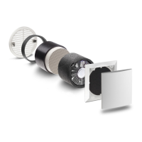
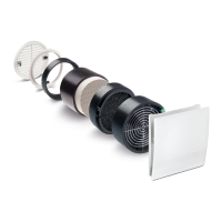
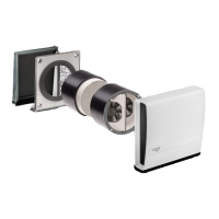
Assembly:
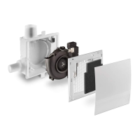
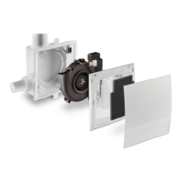
Step 1 - Make the wall openings for the assembly tubes (Ø160 mm) by using hole saw bit Ø162 mm. When installing
in timber frame, fix to timber and seal with Proclima grommet (which is supplied) to building wrap or like. Tube to
have slight 3 mm fall to outside. If necessary, shorten the pipe to the required installation length (min. 190mm). Take
care that the tube overlaps on the outside of the cladding as its sits around 5 to 10 mm inside the external
aluminium grilles. The PVC tubes sits flush with the inside of the GIB. (The PVC tube to have a slit cut out on the
inside, to allow cable entry - image on next page).
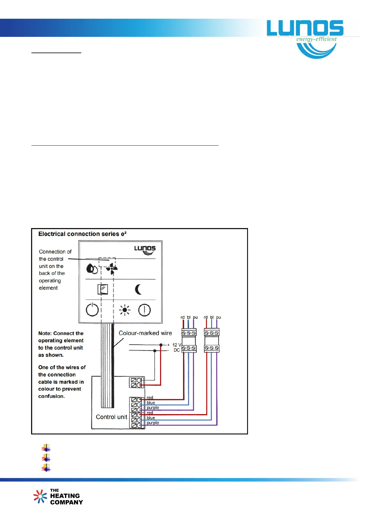
Electrical Installation, electrical Connection & safety instruction:
Step 2
Transformer can be localized (18W transformer) near the flush box for smart comfort controller (5/SC-FT) or
installed it in the switch board (60W transformer). Install 240 V power cabling to the transformer and then run CAT6
cabling to Controller +ve and -ve. Then run CAT6 cables to each e
2
unit
(S1, +ve, -ve or S2, +ve, -ve) as below diagram.
Note: Use KAT 6 ISZH, KAT 5e ISZH or KNX ISZH cables for SIPS panel houses.
Make sure that the supply voltages of all circuits are disconnected.
Each electrical circuit of this ventilation system must be fitted with a residual current protection (RCD).
Electrical connections are to be completed only by a qualified electrician.