CDA3000 Operation Manual
2-7
2 Mechanical installation
1
2
3
4
5
A
DE
EN
FR
IT
ES
FR
2.5 Push-through
heat sink (Dx.x)
Step Action Comment
1
Mark out the positions of the tapped
holes and the breakthrough on the
backing plate.
Cut a tap for each fixing screw in the
backing plate.
Dimensional drawings/hole
spacing - see Table 2.6.
The tapping area will provide
you with good, full-area contact.
2
Mount the inverter module vertically on
the backing plate. Tighten all screws to
the same tightness.
Pay attention to the mounting
clearances! The mounting seal
must contact flush on the sur-
face.
3
Mount the other components, such as the
mains filter, line choke etc., on the
backing plate.
Mains filter max. 20 cm below
the inverter module
4
Continue with the electrical installation in
section 3.
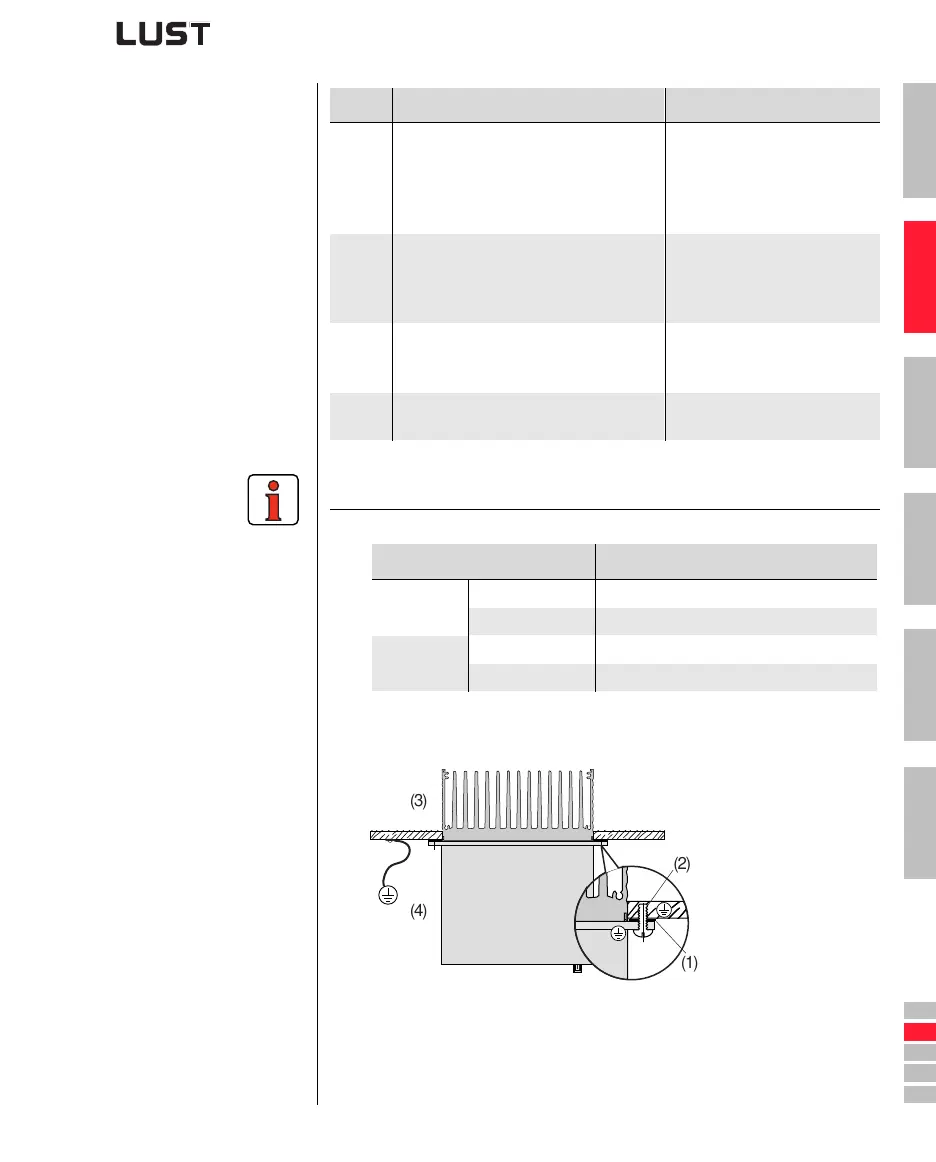
Note the following points:
• Distribution of power loss:
• The all-round mounting collar must be fitted with a seal. The seal
must fit flush on the surface and must not be damaged:
(1) Seal
(2) Tapped hole for
EMC contact
(3) Outside
(4) Inside
• The backing plate must be well grounded.
• The best result for effective EMC installation is attained with a chro-
mated or galvanized backing plate. If backing plates are varnished,
the coating must be removed in the area of the contact surface!
BG3 BG4 BG5 BG6
Power loss
Outside (3) 70% 75% 80% 85%
Inside (4) 30% 25% 20% 15%
Protection
Heat sink side (3) IP54 IP54 IP54 IP20
Machine side (4) IP20 IP20 IP20 IP20
(1)
(4)
(3)
(2)