CDA3000 Operation Manual
3-3
3 Electrical installation
1
2
3
4
5
A
DE
EN
FR
IT
ES
FR
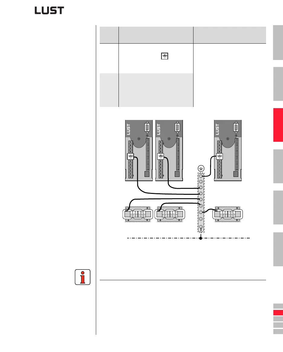
3.2 Grounding lead
connection
Figure 3.2 Star configuration layout of the grounding lead
Step Action
Comment: PE mains connection
to VDE 0100 part 540
1
Ground every inverter module!
Connect terminal X1/
in star
configuration to the PE-rail (main
ground) in the switch cabinet.
Mains connection < 10 mm²
:
Use grounding lead (PE) cross section
min. 10 mm²
or
2 wires with cross-
section of mains leads.
Mains connection > 10 mm²:
Use grounding lead (PE) cross section
according to cross-section of mains
leads.
2
Also connect the grounding lead con-
nections of all other components,
such as the line choke, filter, etc., in
star configuration to the PE-rail
(main ground) in the switch cabinet.
Note the following points:
• The grounding lead must be laid out in star configuration to conform
to the EMC standards.
• The backing plate must be well grounded.
• The motor cable, mains lead and control cable must be laid
separately from each other.
• Avoid loops, and lay cable over short distances.
• The operational leakage current is > 3.5 mA.
W1
V2
W2
U2
U1
V1
W1
V2
W2
U2
U1
V1
W1
V2
W2
U2
U1
V1
PE