4-6
CDA3000 Operation Manual
4 Commissioning
Note: If the power output of the connected motor differs greatly from
the rating of the inverter module, the motor characteristic and
motor monitoring must be adapted. The same applies to spe-
cial motors, multi-pole motors, etc. Refer to the Application
Manual.
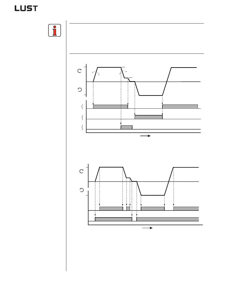
Input signals
Figure 4.1 Example of a quick jog/slow jog driving profile for two directions of
rotation
Output signals
Figure 4.2 Output signals as a function of driving profile
H11 = Reference reached; K3 = Motor holding brake
t [ms]
0
0
1
0
1
0
1
STR
STL
S1
FMAX
f [Hz]
FMAX
303-FMAX1
594-STPR1590-ACCR1
270-FFIX1
t [ms]
0
1
0
1
K3
H11
0
FMAX
f [Hz]
FMAX