CDA3000 Operation Manual
4-15
4 Commissioning
DE
EN
FR
IT
ES
FR
1
2
3
4
5
A
4.7 Operation with
K
EYPAD KP200
The KEYPAD can be plugged directly into the inverter module ( X4).
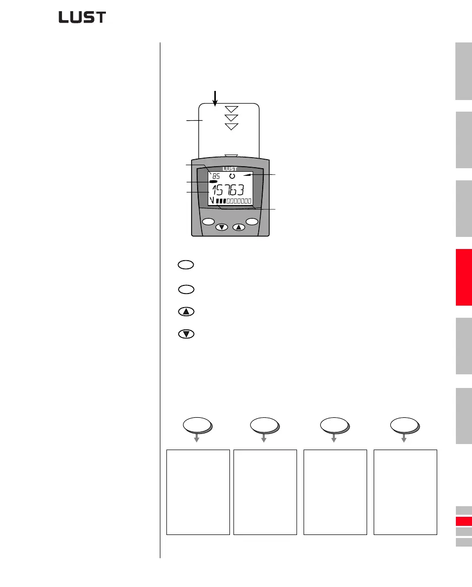
Overview of KEYPAD KP200
Menu structure The KEYPAD KP200 has a user-friendly menu structure which is identical
to that of the KP100 for the S
MARTDRIVE VF1000 inverters and the
M
ASTERCONTROL SERVOCONTROLLERS.
Figure 4.5 Functions of the menus
(1)
SMARTCARD chipcard to save and
transfer settings
(2)
3-digiti display, e.g. for parameter
number
(3) Current menu
(4)
5-digit display for parameter name and
value
(5) Acceleration or braking ramp active
(6) Bar graph display, 10-character
Call up menu branches or parameters; Save changes;
Start in “Control drive” mode
Quit menu branches; Cancel changes; Stop in “Control drive” mode
Select menu, subject area or parameter; Increase setting
Select menu, subject area or parameter; Reduce setting
Table 4.3 Operating and display elements of the KEYPAD KP200
SMART
C A R D
start
enter
stop
return
VAL
Hz
(2)
(1)
(6)
(4)
(3)
(5)
start
enter
stop
return
Actuals
•select
•display
Capacity indicator
Subject area
• select
Parameter
• select
• change
Initial
commissioning
Drive
• control
SMARTCARD
•read
•write
•Write
protection
VAL
PARA
CTRL
CARD