2-2
CDA3000 Operation Manual
2 Mechanical installation
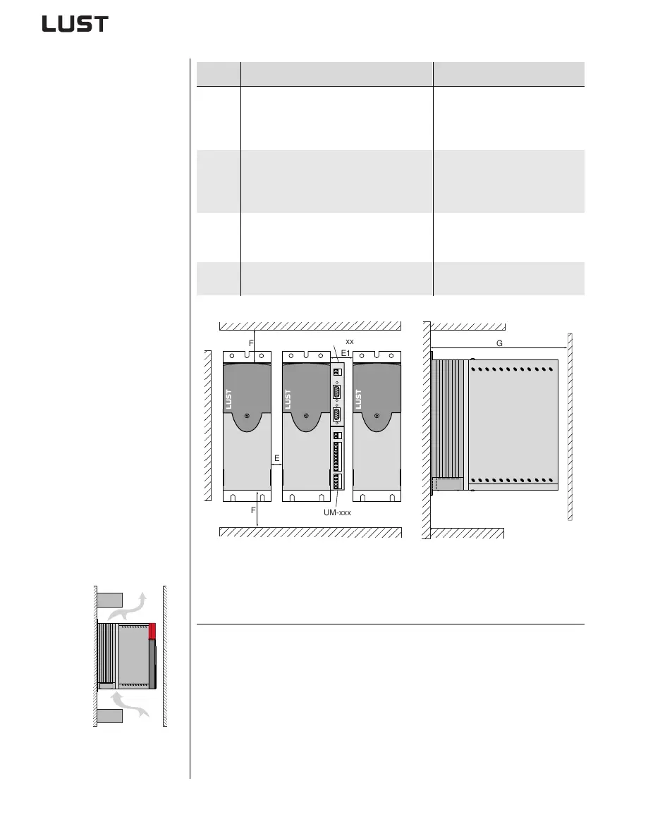
2.3 Wall mounting
Figure 2.1 Mounting clearances (see Table 2.2)
Step Action Comment
1
Mark out the position of the tapped holes
on the backing plate.
Cut a tap for each fixing screw in the
backing plate.
Dimensional drawings/hole
spacing - see Table 2.2
The tapping area will provide
you with good, full-area contact.
2
Mount the inverter module vertically on
the backing plate.
Pay attention to the mounting
clearances!
The contact surface must be
metallically bright.
3
Mount the other components, such as the
mains filter, line choke etc., on the back-
ing plate.
Mains filter max. 20 cm below
the inverter module
4
Continue with the electrical installation in
section 3.
Note the following points:
• Air must be able to flow unhindered through the device.
• The backing plate must be well grounded.
• The best result for effective EMC installation is attained with a chro-
mated or galvanized backing plate. If backing plates are varnished,
the coating must be removed in the area of the contact surface!
F
E
E1
G
F
UM-xxxx
CM-xxxx