EasyManua.ls Logo

Lutron Electronics PHPM-PA-DV-WH - User Manual

Lutron Electronics PHPM-PA-DV-WH
88 pages
Print Icon
To Next Page IconTo Next Page
Loading...
1Power Modules
English
Power Modules
Installation Instructions
Please Read
Switching
Power Module
Phase-Adaptive
Power Module
3-Wire Fluorescent
Power Module
Models and Capacities
Module Type Control Feed* Load Feed** Load Capacity Model Number
Phase-Adaptive 120 V~ 120 – 277 V~ 16 A PHPM-PA-DV-WH
Phase-Adaptive 120 V~ 120 V~ 16 A PHPM-PA-120-WH
3-Wire Fluorescent 120 V~ 120 – 277 V~ 16 A PHPM-3F-DV-WH
3-Wire Fluorescent 120 V~ 120 V~ 16 A PHPM-3F-120-WH
Switching 120 V~ 120 – 277 V~ 16 A PHPM-SW-DV-WH
Phase-Adaptive 220 – 277 V~ 120 – 277 V~ 16 A PHPM-PA-277/DV
* All models except PHPM-PA-277 / DV work with 120 V~ dimmer / control only.
** All units operate at 50 / 60 Hz.
Note: “DV” in model number indicates the load circuit can be 120 277 V~.
P/N 032530a
English Español Français Português
中文
Question and Answer IconNeed help?

Do you have a question about the Lutron Electronics PHPM-PA-DV-WH and is the answer not in the manual?

Overview

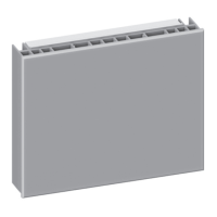
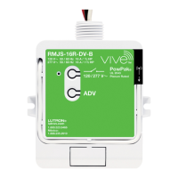
This document describes Lutron Power Modules, which are devices designed to control various lighting loads. The manual provides installation instructions, technical specifications, wiring diagrams, and troubleshooting information for three main types of power modules: Phase-Adaptive, 3-Wire Fluorescent, and Switching. These modules are intended for indoor use and must be installed by a qualified electrician in accordance with all applicable regulations.

Function Description:

Lutron Power Modules serve as an interface between a control unit (like a GRAFIK Eye QS, HomeWorks QS, or Lutron in-wall dimmer) and the lighting load. They allow for dimming or switching of different load types, extending the control capabilities of Lutron systems.

  • Phase-Adaptive Power Module: This module is designed for dimming incandescent (tungsten), halogen, magnetic low-voltage transformer (iron core), electronic (solid-state) low-voltage transformer, and neon/cold-cathode loads. It offers both 120 V~ and 220-277 V~ control feed options, with load feeds of either 120 V~ or 120-277 V~.
  • 3-Wire Fluorescent Power Module: This module is specifically for dimming 3-wire fluorescent ballasts and LED drivers, including Lutron Hi-lume, Hi-lume 3D, Compact SE, EC5 dimming ballasts, and L3D LED drivers. It supports a 120 V~ control feed and offers load feeds of 120 V~ or 120-277 V~.
  • Switching Power Module: This module provides on/off switching for a wide range of loads, including incandescent (tungsten), halogen, LED, CFL, magnetic low-voltage transformer (iron core), electronic (solid-state) low-voltage transformer, magnetic and electronic fluorescent lamp ballasts, neon/cold-cathode, HID, and motor loads. For motor loads, it supports 1/2 HP at 120 V~ and 1/2 HP at 277 V~. It uses a 120 V~ control feed and a 120-277 V~ load feed.

Important Technical Specifications:

  • Load Capacity: All listed models have a load capacity of 16 A.
  • Control Feed:
    • Most models (PHPM-PA-DV-WH, PHPM-PA-120-WH, PHPM-3F-DV-WH, PHPM-3F-120-WH, PHPM-SW-DV-WH) operate with a 120 V~ dimmer/control only.
    • The PHPM-PA-277/DV model is designed for a 220-277 V~ control feed.
  • Load Feed:
    • "DV" in the model number indicates the load circuit can be 120-277 V~.
    • Models without "DV" (e.g., PHPM-PA-120-WH, PHPM-3F-120-WH) are for 120 V~ load circuits.
  • Frequency: All units operate at 50/60 Hz.
  • Wiring:
    • Provide 12 AWG (2.5 mm²) copper wires (75 °C minimum) for input power and load circuit.
    • Strip 1/2 in (12 mm) insulation from wires before connecting.
    • Tighten securely to 4.8 in-lbs (0.55 N•m).
    • Run separate neutral for load circuit; no common neutrals.
  • Dimensions:
    • Front View (all modules): 6.3 in (160 mm) wide, 5.1 in (129.5 mm) high.
    • Side View (Phase-Adaptive Module): 1.2 in (30.5 mm) deep (top), 1.4 in (35.5 mm) deep (bottom).
    • Side View (3-Wire Fluorescent/Switching Modules): 1.2 in (30.5 mm) deep (top), 1.0 in (25 mm) deep (bottom).
  • Operating Temperature: 32 °F to 104 °F (0 °C to 40 °C).

Usage Features:

  • Compatibility: These power modules are compatible with various Lutron control products, including GRAFIK Eye QS control units, GRAFIK Eye 3000 Series control units, LP, LCP, GP dimming panels, HomeWorks QS remote power panels, HomeWorks QS in-line dimmers, HomeWorks QS DIN rail power modules, Energi Savr Node phase adaptive DIN modules, and Lutron in-wall neutral wire dimmers (refer to the Dimmers and Switches Specification Guide for approved lists).
  • Mounting:
    • Mount in a 2-gang U.S. wallbox 3.5 in (89 mm) deep or a 4 × 4 in (102 × 102 mm) junction box 2.1 in (53 mm) deep.
    • Mount with arrows facing upward to ensure adequate cooling.
    • Allow 4.5 in (114 mm) above and below the unit and between faceplates when mounting several in a vertical layout.
    • Mount within 7° of true vertical.
    • When mounting inside an enclosure with GRAFIK Eye control units, proper ventilation is required, and ambient temperature must remain within 32 °F to 104 °F (0 °C to 40 °C). A minimum spacing of 4.5 in (110 mm) is required between units.
  • Wiring Configurations: The manual details several wiring configurations, including single-feed wiring with GRAFIK Eye QS (for 120 V~ and 220-240 V~ applications), dual-feed wiring with GRAFIK Eye QS (for 120 V~ control and 120-277 V~ load), and multiple power modules to a single device. It also shows wiring with a 3-wire fluorescent dimmer and an ESN Phase-Adaptive DIN Module.
  • Overload Protection (Phase-Adaptive/Fluorescent): These modules contain circuitry that will shut down the output if overloaded.

Maintenance Features:

  • Safety Precautions:
    • WARNING: Shock Hazard. Always turn OFF circuit breakers or remove main fuses from the power line before any work. Failure to do so can result in serious personal injury or death. More than one disconnect may be required. Disconnect all power sources before servicing.
    • Improper wiring can result in personal injury, damage to the interface, or damage to other equipment.
  • Troubleshooting (Diagnostics and Troubleshooting section, pages 16-17):
    • Module Status (Green/Orange LED):
      • OFF: Module not powered. (WARNING: Shock Hazard. Control input may still be powered. Turn OFF all breakers before removing unit.)
      • 1 blink/second (slow): Module powered; normal operation.
      • 10 blinks/second (fast): Protection Mode.
    • Output Status (Red LED):
      • OFF: Input signal OFF or disconnected, load OFF.
      • Continuously ON: Incandescent/electronic dimming (Phase-Adaptive), Load ON (3-Wire Fluorescent/Switching).
      • 1 blink/second (slow): Magnetic dimming (Phase-Adaptive).
      • Protection Mode (Red LED blinks, pauses, repeats):
  • 1 blink: Load short-circuit. (Solution: Remove power; repair fault; re-apply power.)
  • 2 blinks: Over-voltage error. (Solution: Verify proper load on output.)
  • 3 blinks: Shorted component. (Solution: Internal device is damaged; replace power module.)
  • 4 blinks: Load Overload. (Solution: Remove power; reduce load; re-apply power.)
  • Dimmed Magnetic Low-Voltage Transformers Note: To avoid overheating and failure, do not operate the module with all lamps removed or inoperative, replace burned-out lamps immediately, and use only transformers with thermal protection or fused primary windings.
  • Plastic Faceplate: The plastic faceplate must be installed on the module for normal operation (all models).
  • Heat Generation: The device generates heat; mount only where ambient temperature is within the specified range (32 °F to 104 °F / 0 °C to 40 °C).
  • Wiring Distance: Mount so line (mains) voltage wiring is at least 6 ft (1.8 m) from sound or electronic equipment and wiring.

Lutron Electronics PHPM-PA-DV-WH Specifications

General IconGeneral
BrandLutron Electronics
ModelPHPM-PA-DV-WH
CategoryControl Unit
LanguageEnglish

Related product manuals