EasyManua.ls Logo

Lutron Electronics Grafik Eye GRX-4000 Series - User Manual

Lutron Electronics Grafik Eye GRX-4000 Series
44 pages
To Next Page IconTo Next Page
Loading...
Installation, Operation, and Maintenance Manual
GP
DIMMING
PANEL
4000
SERIES
CONTROLS
&

Other manuals for Lutron Electronics Grafik Eye GRX-4000 Series

Questions and Answers:

Lutron Electronics Grafik Eye GRX-4000 Series Specifications

General IconGeneral
TypeLighting Control System
Operating Temperature32°F to 104°F (0°C to 40°C)
Control Methodremote control
Power Supply120V AC, 60Hz
Load TypeIncandescent, Magnetic Low Voltage, Electronic Low Voltage
Frequency60Hz
ControlLocal and remote control
Maximum Load per Zone1200W (incandescent), 500VA (magnetic low voltage), 300VA (electronic low voltage)
Dimensions12.5" H x 8.5" W x 3.5" D (31.8 cm x 21.6 cm x 8.9 cm)

Summary

System Overview

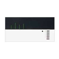
GRX-4000 Series Control Unit Components

Diagram illustrating the key components of the GRX-4000 Series Control Unit.

GRAFIK Eye GP Lighting Control Panel Components

Diagram showing the major components of the GRAFIK Eye GP Lighting Control Panel.

Panel and Wallbox Mounting

Step 1: Mount Wallboxes

Guidance on selecting and installing wallboxes for control units and wallstations.

Step 2: Mount GP Panels

Dimensions, conduit entry, and mounting suggestions for all GP panel types.

Wiring Procedures

Step 3: Control Wiring

Guidelines and specifications for establishing control wiring connections within the system.

Link A Control Wiring

Detailed instructions for wiring Link A, including 1-to-1 connections and cable types.

Link B and DMX Control Wiring

Instructions for Link B wiring, including DMX integration and wiring tables.

Feed and Load Wiring

Step 4: Feed and Load Wiring

Specifications for connecting feed wiring and load circuits to the GP panels.

Load Wiring Types

Details on selecting load types for dimmable and non-dimmable circuits.

Control Unit Configuration

Step 5: Set Address Switches

Procedure for setting address switches on control units and wallstations.

Step 6: Set Function Switches

Guide to setting function switches on wallstations and interface controls.

System Installation and Activation

Step 7: Install Wallstations

Instructions for physically installing wallstations after wiring and configuration.

Step 8: Activate Loads in Bypass

Procedure for activating loads in bypass mode to check wiring.

Step 9: Activate Control Units

Steps to activate control units and verify system communication.

Zone and Load Type Assignment

Step 10: Assign Load Types

How to assign specific load types to circuits using the Circuit Selector.

Step 11: Address GRX-4000 Control Units

Procedure for addressing GRX-4000 Series Control Units within the system.

Step 14: Assign Primary Zones

Steps for assigning primary zones to control units via the Circuit Selector.

Step 15: Set Up Non Dim Zones

Configuring non-dim zones to match load intensity on GRX-4000 Series.

Advanced Control Settings

Step 16: Set Low or High End

Optional adjustment of low and high end light levels for circuit dimming.

Step 17: Set Normal;Emergency Switch

Configuring the switch for normal or emergency lighting circuit operation.

Step 18: Set Up Scenes on GRX-4000

Procedure for setting up and adjusting lighting scenes on GRX-4000 Series units.

Wallstation and Interface Setup

Step 19: Set Up Wallstations

Steps to configure wallstations to listen to control unit button presses.

Wallstation and Interface Operation

Making control units listen and taking them out of set-up mode.

Control Unit Reference Sheets

Save Options Reference

Instructions for accessing and selecting different save options on control units.

16 and 24 Zone GRX Control Units Reference

Information on addressing and assigning zones for 16 and 24 zone GRX units.

Control Directory Reference

Guidance on using the Control Directory for job records and maintenance.

Circuit Selector Reference

Circuit Selector Functions Reference

Details on the functions and capabilities of the Circuit Selector interface.

Circuit Selector Address Reference

Procedure for assigning addresses to Circuit Selectors for system communication.

Connectivity Reference

2 Link Options Reference

Explanation of 2Link options and assigning link hierarchy for circuit control.

2 Link Options - Assign Link Hierarchy

Detailed steps for assigning link hierarchy within the 2Link system.

Panel Internal Views Reference

GP3 and GP4 Panel Internal View

Internal component layout and notes for GP3 and GP4 panels.

GP8 through 24 Panel Internal View

Internal component layout and notes for GP8, 12, 16, 20, and 24 panels.

Wiring Information Reference

Fluorescent Wiring Information

Information on wiring fluorescent ballasts and fixtures for dimming.

Fluorescent Wiring Installation Check

Checks required for existing fixtures when installing fluorescent dimming ballasts.

Neon Tube Application Information

Guidelines for dimming neon and cold-cathode lighting sources.

Neon Tube Luminous Tube Length Chart

Chart for determining luminous tube length for neon/cold-cathode dimming.

Troubleshooting and Maintenance

Troubleshooting Guide

Guide to identifying and resolving common system symptoms and issues.

Troubleshooting Guide Continued

Additional troubleshooting steps and possible causes for system problems.

Maintenance Procedures

Recommended maintenance tasks for control units and fluorescent fixtures.

Glossary of Terms

Glossary of Terms

Definitions of technical terms used throughout the installation manual.

Related product manuals