System Operation
3-2 FOT Lab Kit User’s Manual
Connecting and
Installing the
System
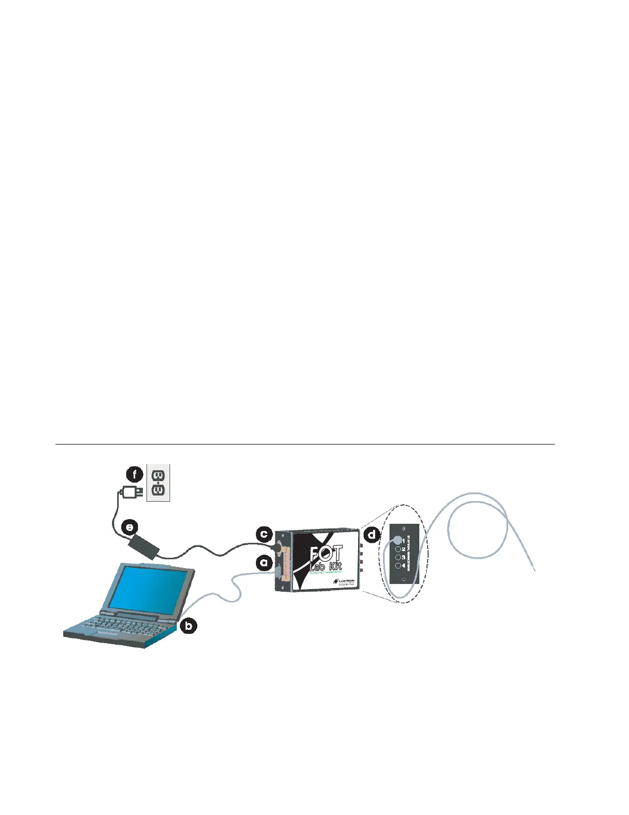
The FOT Lab Kit includes various cables and accessories for
connection. Follow the steps below and refer to Figure 3-1 to setup
the system for operation:
a. Connect the 9-pin male D-sub connector to the RS-232 port
on the instrument.
b. Connect the RS-232 female connector to your computer’s
serial COM port.
c. Connect the power supply’s DIN connector to instrument’s
power inlet.
d. Remove the black dust cap(s) from the instrument’s ST
optical connection(s) and remove the clear protective cap
from your Fluoroptic
®
probe(s). Connect the probe(s) to the
instrument by aligning the polarized connector on the probe
to the optical port and gently push in. Turn clockwise to lock
the connection.
e. Plug power cord into the power supply
f. Plug power supply to a grounded power outlet.
Figure 3-1 Connecting the FOT Lab Kit Components
Fluoroptic Probe
Artisan Technology Group - Quality Instrumentation ... Guaranteed | (888) 88-SOURCE | www.artisantg.com