Step 2: Unplug the 3-position screw terminal (black) from
Step 3:
Step 4: Insert the negative wire from your 24 Vac/dc, 50/60 Hz
circuit to the terminal marked ~/- on the screw terminal
and tighten down the screw.
Step 5: Insert the ground wire from your 24 Vac/dc, 50/60 Hz
on the
circuit to ground (far left terminal) marked
screw terminal and tighten down the screw.
Step 6: Plug the 3-position screw terminal connector back
into the Power port on the JENEsys Edge 414.
Step 7: Temporarily change your computer’s network settings so your IP address is in
the range: 192.168.1.1 to 192.168.1.254 (without using the JENEsys Edge 414’s
default address as described in Step 8). Make note of your computer’s current
network settings.
Step 8: With ProBuilder (Workbench) 4.10.1/4.9.1/4.7.110 installed on your computer,
make a Platform connection to the JENEsys Edge 414 using the factory default IP
address (192.168.1.12n, where the last numeral (n) matches the last numeral in
the JENEsys Edge 414’s Host ID number), platform daemon port (3011), and
the following credentials:
Username: tridium
Password: niagara
Step 9: Refer to the GETTING STARTED WITH NIAGARA 4 GUIDE and JENESYS EDGE 414
USER GUIDE for detailed instructions on how to configure it using Niagara 4.
Package Contents of JENE-EG414
Estimated completion time: 5-10 minutes
(1) JENEsys Edge 414 (JENE-EG414)
This JENEsys Edge 414 Installation Guide
(1) JENEsys Edge 414 Wiring Installation Guide
(3) 6-Position Terminal Connectors (2 black & 1 blue)
(5) 3-Position Terminal Connectors (2 black, 1 gray & 2 blue)
Preparing to Install
Decide on the location/placement of your JENEsys Edge 414, ensuring its position is
upward/vertical. You can use wall mounting screws (not provided) to mount the device in an
open space or mount on a 35mm wide DIN rail utilizing the molded DIN rail slot
located on the base of the device. Make sure the selected location is:
Not in direct sunlight or near a heater or heating vent
Not cluttered/crowded and sufficient clearance is available above and below the
JENEsys Edge 414 for proper ventilation and room for cables and wiring
Well-ventilated (especially if enclosed in a cabinet)
This device has been loaded with the bare minimum Niagara 4.2.36 software and requires
the latest Onyxx Driver package to commission and update the controller's firmware.
Download the latest N4 version of the required Onyxx Driver package at:
resources.lynxspring.com.
Physical Mounting to a DIN Rail
For UL safety compliance this Lynxspring product shall be mounted inside enclosures with no
openings below the device and if non-metallic, a flammability rating of at least HB.
Step 1: Pull out the DIN rail clip and push down and in to force the DIN rail clip to snap
over the other edge of the DIN rail.
Step 2: Pull out the DIN rail clip and push down and in to force the DIN rail clip to snap
over the other edge of the DIN rail.
Step 3: To keep the JENEsys Edge 414 from sliding on the DIN rail, secure it with clips
provided by the DIN rail vendor, or place a screw in one of the mounting tabs in
the base of the JENEsys Edge 414.
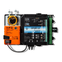
Note 1: Up to three Onyxx XM 34IOs can be connected. See section:
CONNECTING ONYXX NETWORKS TO JENESYS EDGE 414 for details.
Note 2: To remove the device(s) from a DIN rail, insert a screwdriver in center plastic
locking t
ab and pull downwards, then lift the unit outwards.
Connecting to the JENEsys Edge 414
A 10/100-Mbit Ethernet connection is available on the JENEsys Edge 414. The
RJ-45 port has two LED
s. When the device is connected to a network, the blue LINK LED is lit
and the blue ACTIVI
TY LED flashes when activity occurs.
Step 1: Connect one end
of the Ethernet cable to your
JENEsys Edge 414
’s Primary RJ-45 port and the
other end to the internet port on your
computer.
the Power port on
the JENEsys Edge 414.
Insert the positive
wire from your 24 Vac/dc, 50/60 Hz
circuit to the termi
nal marked ~/+ on the screw terminal
and tighte
n down the screw.
RECOMMENDED RS-485 CABLE SPECIFICATION
Max Cable Length 4,000 feet
Min loaded driver output signal level ± 1.5v
Driver load impedance (Ohms) 54
Receiver input voltage range -7v to + 12v
Receiver input resistance (Ohms) ≥12k
C
onnecting RS-485 Networks to JENEsys Edge 414
The RS-485 ports use a 3-position, screw terminal connector. The screw
terminals (from left-to-right) are shield, negative (-), and positive (+). The transmit
(Tx) and receive (Rx) LEDs located on the JENEsys Edge 414 cover will flash when there
is network activity detected.
Step 1: Unplug 3-position screw terminal connector
from either RS-485 port on the device.
Step 2: Insert positive wire from your RS-485 network
to positive terminal (far right terminal) on the
3-position, screw terminal connector and
tighten down the screw.
Step 3: Insert negative wire from your BACnet network to
negative terminal (center terminal) on the 3-position, screw
terminal connector and tighten down the screw. Please
refer to the JENESYS EDGE 414 WIRING INSTALLATION GUIDE for
further wiring instructions and cautions.
Step 4: Lynxspring recommends installing a 120-ohm end-of-line resistor on the
positive (+) and negative (-) terminals.
Step 5: Plug 3-position screw terminal connector back into the RS-485 port.
RS-485 Network
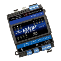
JENEsys Edge® 414
INSTALLATION GUIDE
Ma
de in USA
Ethernet Cable
Connection from
device to computer
24 Vac/dc Power