Do you have a question about the Lynxspring ONYXX LX BZ424-LX and is the answer not in the manual?
| power supply voltage | 24 VAC/VDC ± 15% |
|---|---|
| current consumption | 5 VA |
| maximum current consumption | 48 VA |
| voltage range | 0 - 10 Vdc |
| current range | 0 - 20 mA |
| dimensions | 4.9” x 8.5” x 2.5” |
|---|---|
| dimensions (metric) | 123 mm X 215 mm X 63 mm |
| weight | 744 g / 1.5 lb |
| noise level | 35 dB(A) |
| shaft diameter | 1/4” to 5/8” [6mm to 16mm] |
| stocking temperature range | -30 °C to 50 °C / -22 °F to 122 °F |
|---|---|
| operating temperature range | -25 °C to 45 °C / -13 °F to 113 °F |
| operating humidity range | 10% to 90% H.R. without condensation |
| microprocessor | STM32 (ARM CortexTM M3) 32 bits |
|---|---|
| cpu speed | 72MHz |
| memory | 768 KB non-volatile Flash |
| ram | 96 KB RAM |
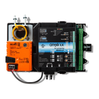
Provides instructions for mounting the BZ424 controller to ductwork or sheet metal.
Describes the product label on the removable cover for identifying internal interfaces.
Details wiring connections for the controller, including cable specifications for RS-485 networks.
Explains wiring for MS/TP, TZ Comm Bus, and power connections to the controller.
Details the configuration of DIP switches and jumpers for various controller settings.
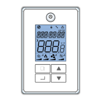
Explains how to connect TZ room sensors in a daisy-chain configuration.
Configures the controller to manage room temperature using TZone sensors.
Details cooling and heating control strategies for occupied and unoccupied modes.
Describes standby control modes based on motion sensor input.
Explains how the system switches between heating and cooling modes.
Covers limiting heating outputs and using fan status for airflow verification.
Details sequence logic to prevent condensation in specific fan applications.
Explains series and parallel fan powered application control logic.
Describes condensate avoidance logic using MSV-70 settings.
Details the sequence for ventilation control based on CO2 sensor readings.
Details settings for maximum and minimum airflow in heating and cooling modes.
Explains the setting for the internal airflow actuator's runtime.
Explains DCV application using CO2 sensors and setpoints.
Describes condensate avoidance based on dewpoint readings and chilled water temperature.
Details PID parameters (Kp, Ki, Bias) for various control loops.
Illustrates the flow control PID loop with setpoints and output.
Details dependent and independent pressure control logic for VAV systems.
Explains control logic for auxiliary outputs in heating modes.
Explains control logic for auxiliary outputs in cooling modes.
Details logic for parallel and series fan types with auxiliary outputs.
Describes control logic for series fan types in occupied/unoccupied modes.
Details methods for connecting multidrop RS-485 networks.
Illustrates the recommended daisy-chain topology for RS-485 networks.
Offers tips for diagnosing and resolving issues in RS-485 networks.
Depicts and warns against non-functional RS-485 network topologies like star or ring.