Do you have a question about the Lynxspring onyxx LX BW437-RTU-LX and is the answer not in the manual?
| Brand | Lynxspring |
|---|---|
| Model | onyxx LX BW437-RTU-LX |
| Category | Controller |
| Language | English |
Step-by-step guide for physically attaching the controller to a wall or surface.
Configuration of internal jumpers (JP2, JP3) for specific device functions and network settings.
Details on how to connect the 24VAC transformer and power supply to the controller.
Guidance on connecting input/output wires to the controller's terminal blocks.
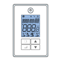
Explanation of the controller's interface buttons and their functions.
Description of icons displayed on the controller's local LCD screen.
Explanation of messages shown on the controller's local LCD for various conditions.
Notes on staging delays for cooling and heating operations based on demand.
Procedure for configuring network settings like address, baudrate, and topology.
Guide to accessing and configuring the controller's setup menu for various applications.
Wiring diagram and sequence of operation for the RT 2STG application.
Wiring diagram and sequence of operation for the RTECON application.
Wiring diagram and sequence of operation for the HP 2STG application.
Wiring diagram and sequence of operation for the RT IAQ application.
Wiring diagram and sequence of operation for the RT MOD application.
Wiring diagram and sequence of operation for the HP DEH application.
Wiring diagram and sequence of operation for the HUM-DEH (RTU) application.
Wiring diagram and sequence of operation for the HUM-DEH (HP) application.
Wiring diagram and sequence of operation for the RT 3STG application.
Wiring diagram and sequence of operation for the RT 4STG application.
Accessing service menus and configuring objects via the keypad.
Performing local tests on controller inputs and outputs.
Configuration parameters for multi-state values MSV1 through MSV6.
Configuration parameters for multi-state values MSV7 through MSV10.
Configuration parameters for multi-state values MSV16 through MSV19.
Configuration parameters for multi-state values MSV23, MSV27, MSV28, MSV30.
Configuration parameters for multi-state values MSV32 and MSV44.
Configuration parameters for multi-state value MSV45.
Configuration parameters for multi-state values MSV48, MSV49, MSV52, MSV54, MSV55, MSV57, MSV58.
Configuration parameters for multi-state values MSV62, MSV64, MSV65.
Configuration parameters for multi-state values MSV66, MSV67, MSV68.
Configuration parameters for multi-state values MSV70 and MSV75.
Configuration parameters for multi-state values MSV100 and MSV127.
Best practices for building robust and reliable RS-485 networks using daisy-chain topology.
Illustrations of network configurations that do not function correctly.