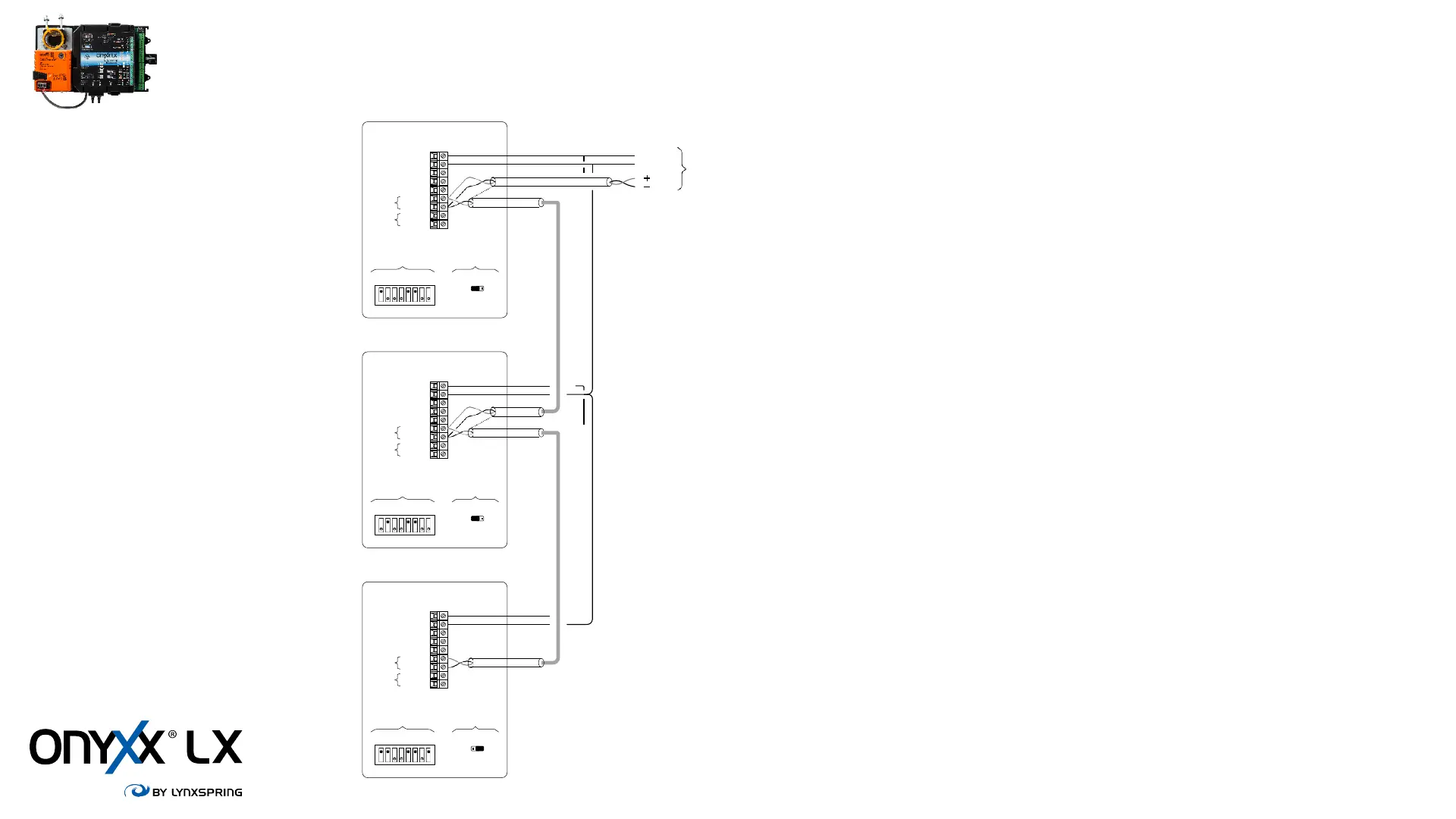
TZ Room Sensor Wiring
• Daisy-chain up to 3 TZ room sensors
• RS-485 wire require
d for communications wiring
• Supported Wire Size 28-16 AWG for
power wiring, recommend 18 AWG
• Max total distance of communicati
on wire of 300 ft from controller to
last TZ room sensor
• Field verify Tzone address
ing and EOL jumpers
• Connect shields together in t
he daisy-chain communication network
(isolate them to avoid touching metal or electronic components)
• Connect shield to ground
, at only one end of the network
• MS/TP A+ and B+ are optio
nal; they are directly connected to the USB
connector below the TZxxx. The goal is to allow access to the MSTP
network from the special USB to MSTP adapter
MS/TP
TZ
DS1
12345678
EOL
TZ100
JP2
NONE EOL
TZ200
COM
24 Vac
A
B
BZxxx
MS/TP
TZ
DS1
12345678
EOL
TZ100
EOLNONE
JP2
TZ200
MS/TP
TZ
DS1
12345678
EOL
TZ100
JP2
NONE EOL
TZ200
COM 1
24VAC 2
N/C 3
UNUSED
AI 4
UNUSED BI 5
A+ 6
B- 7
A+ 8
B- 9
COM 1
24VAC 2
N/C 3
UNUSED
AI 4
UNUSED
BI 5
A+ 6
B- 7
A+ 8
B- 9
COM 1
24VAC 2
N/C 3
UNUSED
AI 4
UNUSED BI 5
A+ 6
B- 7
A+ 8
B- 9
• If there is a loss in communication to any of the TZ controllers, BV24 will indicate a
fault, AV 41 will = - 40 °F and the fan, heating and cooling will be disabled, and the
damper will return to minimum position.
www.lynxspring.com
 Loading...