MOUNTING AND WIRING GUIDE
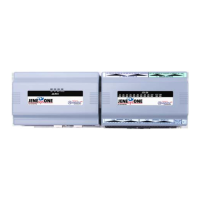
JO-PC1 Base Controller
JENEsysONE™ Equipment Controller
JO-PC1 Base Controller Mounting and Wiring Guide
Part Number JO-PC1 rev 1 Updated: January 16, 2012
1
JENEsysONE and ProBuilder are trademarks and JENEsys is a registered trademark of Lynxspring, Inc.
Niagara Framework, Niagara AX Framework and the Sedona Framework are trademarks of Tridium, Inc.
:
Note Not covered in this document is the Niagara
AX
software installation and configuration required for a
fully functioning unit. This includes setting host IP address and password, serial port configuration, and
other parameters. Refer to the JENE NiagaraAX Install and Startup Guide for this information.
In addition, the mounting and wiring of JENEsysONE
®
expansion options are covered in separate
documents. See sections “Related Documentation,” page 4, and “About Expansion Options,” page 8.
These are the main topics included in this document:
• Preparation, page 2
• Precautions, page 3
• Mounting, page 5
• Board Layout, page 7
• About Expansion Options, page 8
• Wiring Details, page 10
–
Grounding, page 10
–
Power Wiring, page 11
–
Communications Wiring, page 11
–
RS-485 Biasing, page 13
• Power Wiring, page 11
• Using Status LEDs, page 19
• Maintaining the JO-PC1, page 20
• Replacement Parts, page 21
• Certifications, page 24
• Tab Mounting Dimensions, page 26
This document covers the mounting and wiring of the
JENEsysONE
™
equipment controller JO-PC1 base
controller. It assumes that you are an engineer, technician,
or service person who is performing control system
installation. Instructions in this document apply to the
following products:
Models Description
JO-PC1 JO-PC1 base unit controller
JO-34 JO-34 base 34 point I/O module
JO-16 JO-16 optional 16 point I/O module