EM-7801-A Rev.7 P. 4 / 10
TERMINAL CONNECTIONS
Connect the unit as in the diagram below.
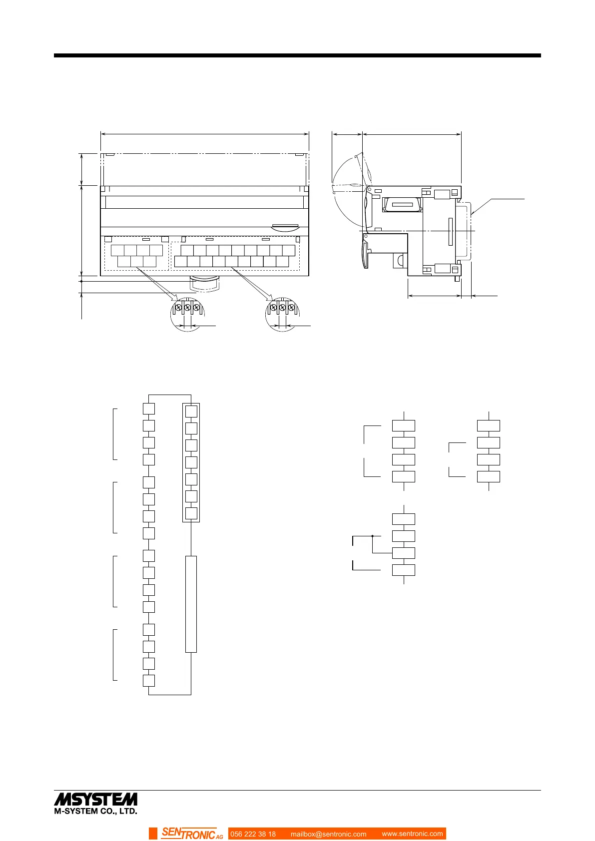
■ EXTERNAL DIMENSIONS unit: mm (inch)
4567
123
10 11 12 13
2341
15 16 17 18
78
9
6
14
5
30 (1.18)
[5 (.20)]
3 (.12)5.5 (.22)
DIN RAIL
35 mm wide
54 (2.13)
17 (.66)
50 (1.97)
18.5 (.73)
115 (4.53)
7–M3 SCREW
TERMINALS
for CC-Link, POWER
18–M3 SCREW
TERMINALS
for INPUT
6 (.24)
6 (.24)
■ CONNECTION DIAGRAM
4
7
6
3
2
5
1
0V
24V DC
FG
SLD
DG
DB
DA
1
VH0
10
VL0
11
I0
2
COM0
INPUT 0
3
VH1
12
VL1
13
I1
4
COM1
INPUT 1
6
VH2
15
VL2
16
I2
7
COM2
INPUT 2
8
VH3
17
VL3
18
I3
9
COM3
INPUT 3
■ Input Connection Examples
VHn
VLn
In
+
–
COMn
WIDE SPAN
VOLTAGE
VHn
VLn
In
+
–
COMn
NARROW SPAN
VOLTAGE
VHn
VLn
In
+
–
COMn
Be sure to close across VLn and In terminals for a current input.
CURRENT
RANGE
EXTENSION CONNECTOR
In order to improve EMC performance, bond the FG
terminal to ground.
Caution: FG terminal is NOT a protective conductor terminal.
4
7
6
3
2
5
1
0V
24V DC
FG
SLD
DG
DB
DA
1
VH0
10
VL0
11
I0
2
COM0
INPUT 0
3
VH1
12
VL1
13
I1
4
COM1
INPUT 1
6
VH2
15
VL2
16
I2
7
COM2
INPUT 2
8
VH3
17
VL3
18
I3
9
COM3
INPUT 3
■ Input Connection Examples
VHn
VLn
In
+
–
COMn
WIDE SPAN
VOLTAGE
VHn
VLn
In
+
–
COMn
NARROW SPAN
VOLTAGE
VHn
VLn
In
+
–
COMn
Be sure to close across VLn and In terminals for a current input.
CURRENT
RANGE
EXTENSION CONNECTOR
In order to improve EMC performance, bond the FG
terminal to ground.
Caution: FG terminal is NOT a protective conductor terminal.
056 222 38 18 mailbox@sentronic.com
www.sentronic.com
SEN
TRONIC AG
 Loading...