EasyManua.ls Logo

M-system 60C User Manual

M-system 60C
13 pages
To Next Page IconTo Next Page
Page #1 background imageLoading...
Page #1 background image
Contents
1. BEFORE USE .... .......................................................................................... 2
2. GENERAL DESCRIPTION ........................................................................... 2
3. POINTS OF CAUTION .................................................................................. 3
4. HARDWARE SPECIFICATIONS .................................................................. 4
4.1. 60C-x1 (No. of channels codes 04, 08, or 16 in x) ........................................................................4
4.2. 60C-x2 (No. of channels codes 04, 08, or 16 in x) ........................................................................4
5. COMPONENT IDENTIFICATIONS & HARDWARE ADJUSTMENTS .......... 5
6. INSTALLATION ............................................................................................ 5
7. TERMINAL CONNECTIONS ........................................................................ 6
8. CONNECTING DATA LINK WIRES .............................................................. 7
8.1. TWISTED-PAIR CABLE ................................................................................................................7
8.2. POINTS OF CAUTION IN HANDLING WIRES .............................................................................7
8.3. WIRING DIAGRAM .......................................................................................................................7
9. WIRING & CONNECTIONS.......................................................................... 8
9.1. POINTS OF CAUTION IN CONNECTING WIRES ........................................................................8
9.2. CONNECTOR PIN ASSIGNMENTS .............................................................................................8
9.3. CABLE (MODEL: MCN34) PIN ASSIGNMENTS ..........................................................................9
10. I/O SIGNALS ...............................................................................................10
10.1. REMOTE I/O ...............................................................................................................................10
10.2. ASSIGNING REMOTE REGISTERS ..........................................................................................10
10.3. A/D CONVERSION ..................................................................................................................... 11
11. PARAMETERS SETTING BY PLC PROGRAM ..........................................12
11.1. GENERAL DESCRIPTION .........................................................................................................12
12. TROUBLESHOOTING .................................................................................13
12.1. L ERR. INDICATOR BLINKING ...................................................................................................13
12.2. L ERR. INDICATOR ON ..............................................................................................................13
12.3. L RUN INDICATOR OFF .............................................................................................................13
12.4. UNABLE TO READ/WRITE DIGITAL VALUES? .........................................................................13
13. LIGHTNING SURGE PROTECTION ...........................................................13
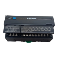
ANALOG I/O MODULE
(CC-Link)
MODEL
60C
5-2-55, Minamitsumori, Nishinari-ku, Osaka 557-0063 JAPAN
Phone: +81(6)6659-8201 Fax: +81(6)6659-8510 E-mail: info@m-system.co.jp
EM-6602 Rev.8 P. 1 / 13
INSTRUCTION MANUAL

Questions and Answers:

M-system 60C Specifications

General IconGeneral
BrandM-system
Model60C
CategoryI/O Systems
LanguageEnglish

Summary

GENERAL DESCRIPTION

PACKAGE INCLUDES

Lists items included in the package for the Analog I/O Module.

MODEL NO.

Explains how to confirm the product's model number marking.

INSTRUCTION MANUAL

Describes the manual's content for usage, installation, and maintenance.

POINTS OF CAUTION

POWER INPUT RATING & OPERATIONAL RANGE

Details power input requirements and operational limits for the unit.

GENERAL PRECAUTIONS

Advises turning off power before removing or mounting the unit for safety.

ENVIRONMENT

Specifies environmental conditions like dust, vibration, temperature, and humidity for proper operation.

WIRING

Provides guidelines for routing cables to avoid noise interference.

HARDWARE SPECIFICATIONS

60C-x1 (No. of channels codes 04, 08, or 16 in x)

Specifies hardware details for 60C-x1 input modules (channels, protocol, I/O, resolution, accuracy, isolation, etc.).

60C-x2 (No. of channels codes 04, 08, or 16 in x)

Specifies hardware details for 60C-x2 output modules (channels, protocol, I/O, resolution, accuracy, isolation, etc.).

COMPONENT IDENTIFICATIONS & HARDWARE ADJUSTMENTS

Modular jack for factory calibration

Describes the function of the modular jack used for factory calibration.

Power LED

Explains the status indication of the green Power LED.

Station No. Setting

Details how to set the CC-Link station number (1-64).

Baud rate Setting

Explains the selectable baud rates for CC-Link communication.

Status indicator LED

Describes the L RUN, L ERR, SD, and RD status indicator LEDs.

INSTALLATION

DIN RAIL MOUNTING

Instructions for mounting the unit onto a 35mm DIN rail.

WALL MOUNTING

Refers to external dimensions for wall mounting instructions.

TERMINAL CONNECTIONS

EXTERNAL DIMENSIONS unit: mm (inch)

Provides physical dimensions of the unit for installation planning.

CONNECTION DIAGRAM

Illustrates how to connect the communication module and power terminals.

CONNECTING DATA LINK WIRES

8.1. TWISTED-PAIR CABLE

Recommends specific types of twisted-pair cables for CC-Link connection.

8.2. POINTS OF CAUTION IN HANDLING WIRES

Lists precautions for handling wires to prevent damage and ensure signal integrity.

8.3. WIRING DIAGRAM

Shows the wiring diagram for connecting the 60C to the Master Unit.

WIRING & CONNECTIONS

9.1. POINTS OF CAUTION IN CONNECTING WIRES

Advises on separating wires and grounding for noise prevention.

9.2. CONNECTOR PIN ASSIGNMENTS

Details pin assignments for input (60C-x1) and output (60C-x2) connectors.

9.3. CABLE (MODEL: MCN34) PIN ASSIGNMENTS

Provides pin assignments for the MCN34 cable and its wiring diagram.

I/O SIGNALS

10.1. REMOTE I/O

Explains the assignment of 32 bits for input/output and the READY signal.

10.2. ASSIGNING REMOTE REGISTERS

Details data assignment for Remote to Master (60C-x1) and Master to Remote (60C-x2) registers.

10.3. A/D CONVERSION

Illustrates the conversion process for analog input (60C-x1) and output (60C-x2), including abnormal output behavior.

PARAMETERS SETTING BY PLC PROGRAM

11.1. GENERAL DESCRIPTION

Shows a ladder diagram example for setting parameters on the master station.

TROUBLESHOOTING

12.1. L ERR. INDICATOR BLINKING

Troubleshooting steps for a blinking L ERR indicator.

12.2. L ERR. INDICATOR ON

Troubleshooting steps for a solid L ERR indicator.

12.3. L RUN INDICATOR OFF

Guidance for troubleshooting when the L RUN indicator is off.

12.4. UNABLE TO READ/WRITE DIGITAL VALUES?

Checks and potential causes for issues reading or writing digital values.

LIGHTNING SURGE PROTECTION

Related product manuals