7. TERMINAL CONNECTIONS
Connect the unit as in the diagram below or refer to the connection diagram on the side of the unit.
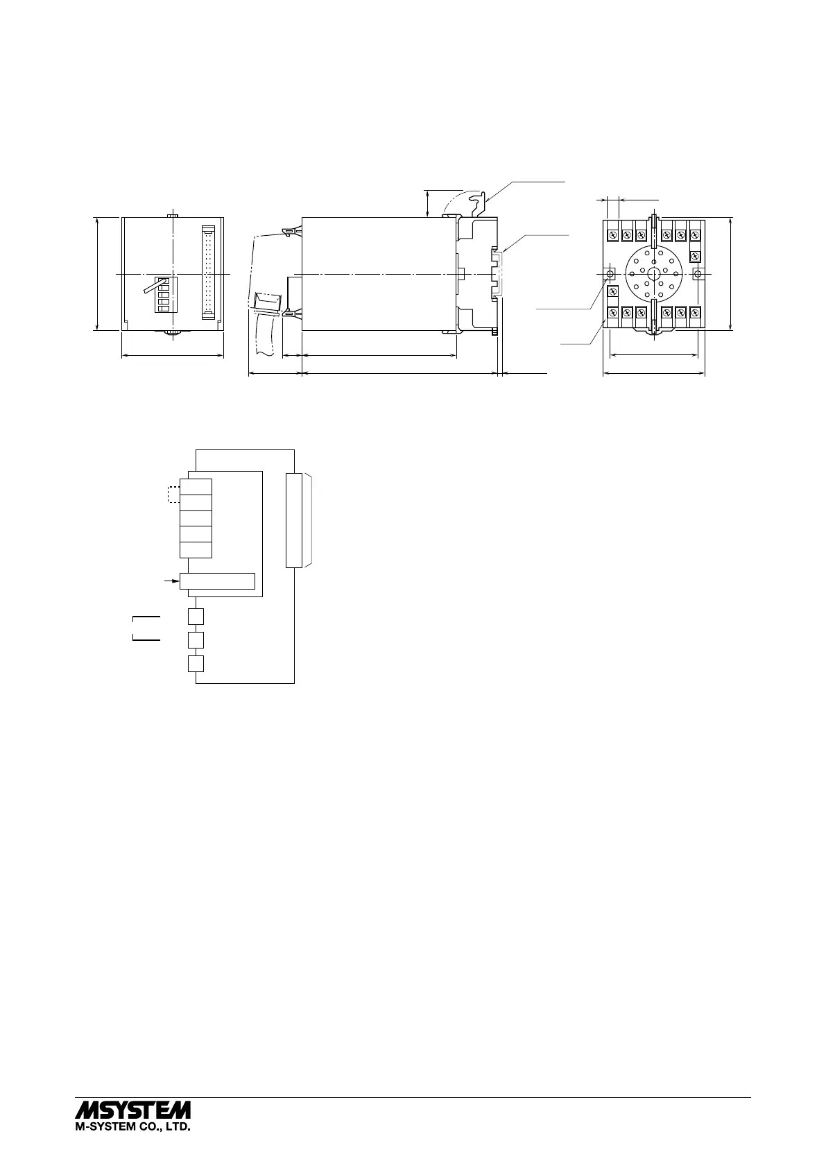
■ EXTERNAL DIMENSIONS unit: mm (inch)
14
(.55)
38 (1.50)
80 (3.15)
72 (2.83) 109 (4.29)
139 (5.47) [3.3 (.13)]
20
(.79)
CLAMP
(top & bottom)
DIN RAIL
35mm wide
•When mounting, no extra space is needed between units.
80 (3.15)
60 (2.36)
72 (2.83)
7.8 (.31)
2–4.5 (.18) dia.
MTG HOLE
25 (.98) deep
14–M3.5
SCREW
12
56
14
11
1
1015
4
3
2
7
9
8
■ CONNECTION DIAGRAM
Modular Jack
for Factory
Calibration
MODULAR JACK
DA
DB
DG
SLD
FG
U(+)
V(–)
POWER
7
14
To Other
CC-Link
Devices
COMM. MODULE
FG1
8
I/O CONNECTOR
Terminator
*
* Attach the terminating resistor when the module is
at the termination of a transmission line.
To 10-Rack,
18-Rack etc.
60C
5-2-55, Minamitsumori, Nishinari-ku, Osaka 557-0063 JAPAN
Phone: +81(6)6659-8201 Fax: +81(6)6659-8510 E-mail: info@m-system.co.jp
EM-6602 Rev.8 P. 6 / 13