Height of centers over bed
Max. Swing diameter over bed
The steps of spingle speeds
Max. turning angle of rest slide
Max. travel of cross slide
Taper bore of the tailstock
0.55kw.230v.50HZ 0.55kw.220v.50HZ 0.55kw.110v.60HZ
±
This is the axis established through the spindle of the headstock. It is
horizontal to and parallel with the lathe bed along its length.
This is the axis established by the work piece, it is horizontal to but not
necessarily parallel with, the lathe bed, along its length.
This is the axis described by the compound slide when it is being operated
independently of the traverse slide and the saddle.
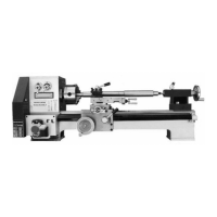
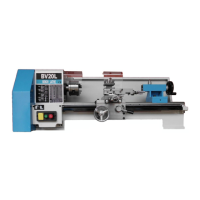
Please take some time to identify the various parts of your machine so that you are familiar
with the terminology we will use to enable you to set up and operate your Lathe safety and
correctly.
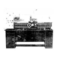
The ‘engine block’ of the lathe, supports the motor, the spindle, contains
the gearbox for the spindle speed selection, mount the change gears
and the driven end of the lead screw.
The rack is fixed on the underside of the front rail of the lathe bed, it is
permanently engaged with the saddle control wheel pinion.
Identification and Description of the parts
 Loading...