Two levers marked “A” and “B” which, in their setting select the different
spindle speeds of the lathe. Refer to the Speed change chart to select
the required speed.
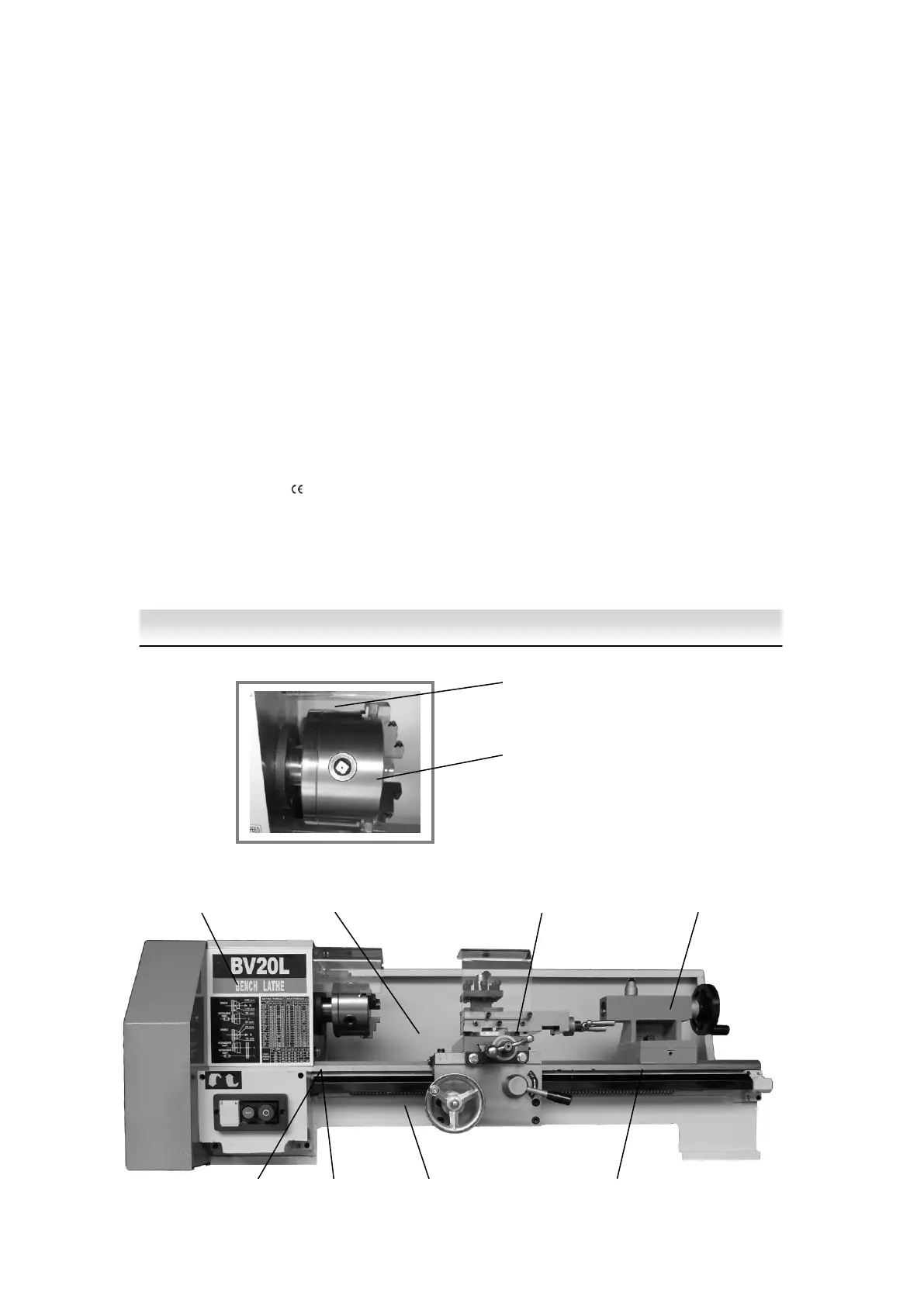
A clear acetate cover mounted on a pivot bar on the rear top front face of
the headstock. It can be tipped out of the way to access the chuck when
It is stationary, and repositioned over the chuck during operation.
Green push button switch marked ‘I’ to start the motor, red push button
switch marked ‘O’ to switch the motor off.
Feed speed
and
thread cutting
gear change
chart
This chart indicates the necessary gears and their positions to enable
the wide range of metric, imperial, module and diameter threads to be
cut and the different feed rate to be achieved. The feed speed is quoted
as a linear distance along the Main Axis per revolution of the leadscrew.
Rocker switch set under a protective cover, (to prevent inadvertent
operation), changing the position of the switch will reverse the direction
of the motor. MAKE SURE THE SPINDLE IS STOPPED BEFORE
OPERATING THIS SWITCH.
Spindle speed
change chart
This is indicates the position of the levers to select the various spindle
speeds.
Fig 1
Machine Illustration and key parts description