Do you have a question about the Mac Afric BV20BL and is the answer not in the manual?
Suggestions for observing good working practices and ensuring safety.
Safety checks for power cables, plugs, and ideal installation environment.
Instructions for preparing a rigid bed and mounting the lathe securely.
Filling headstock oil, checking belt tension, and performing a running-in procedure.
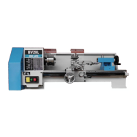
Technical details and measurements of the BV20BL lathe.
Explanations of Main Axis, Work Axis, Traverse Axis, and Compound Axis.
Descriptions of Headstock, Tailstock, Lead screw guard, Tool Post, and Leadscrew.
Descriptions of Motor, Chuck mounting, Tailstock lock, drive handle, and safety covers.
Descriptions of Lathe bed, Saddle, Traverse slide, and Compound slide.
Descriptions of Saddle control, Auto feed lever, and slide control handles.
Descriptions of Tailstock clamp screws, offset screws, and tool post locking handle.
Descriptions of gear levers, switches, and charts for speed, feed, and reversing.
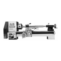
Illustration showing key parts like Chuck, Headstock, Tailstock, Saddle.
Illustrations focusing on the Tailstock and Chuck assembly details.
Illustrations of Compound slide and its control handles.
Illustrations of Tailstock controls and gear change/reversing mechanisms.
Description of the gear compartment door, oil drain plug, and headstock cover plate.
Explanation of the 18T reverse tumbler gear for leadscrew direction control.
Illustrations showing the oil sight glass and oil drain plug.
Illustrations of gearbox covers and the door micro-switch.
Schedule for initial and subsequent gearbox oil changes based on usage hours.
Daily pre-use lubrication, cleaning, and weekly inspection tasks.
Recommendations for specific oils, greases, lubricants, and cutting fluids.
Diagram identifying all oil lubrication points on the lathe (A-H).
Tables for selecting gears for thread cutting and gearbox ratios.
Detailed exploded view with numbered parts for easy identification and replacement.
| Swing Over Bed | 200mm |
|---|---|
| Spindle Bore | 20 mm |
| Spindle Speed Range | 100-2000 RPM |
| Motor Power | 550W |
| Tailstock Taper | MT2 |
| Voltage | 220 V |