OM-210 089 Page 12
SECTION 3 − INSTALLATION
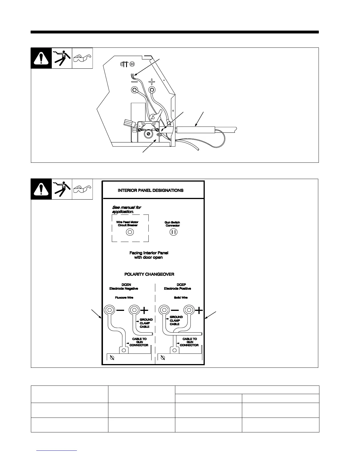
3-1. Installing Welding Gun
Ref. ST-802 024
1 Drive Assembly
2 Gun Securing Thumbscrew
3 Gun End
Loosen thumbscrew. Insert gun
end through opening until it bot-
toms against drive assembly.
Tighten thumbscrew.
4 Gun Trigger Leads
Insert leads, one at a time, through
small grommet on front panel.
Connect female friction terminals
to matching male terminals in unit.
Polarity is not important.
Close door.
4
1
2
3
3-2. Changing Polarity
1 Lead Connections For Direct
Current Electrode Positive
(DCEP)
2 Lead Connections For Direct
Current Electrode Negative
(DCEN)
Always read and follow wire
manufacturer’s recommended po-
larity, and see Section 3-3.
Close door.
1
Ref. ST-802 024
2
3-3. Process/Polarity Table
Cable Connections
Cable To Gun Cable To Work
GMAW − Soild wire with shield-
ing gas
DCEP − Reverse polarity Connect to positive (+) out-
put terminal
Connect to negative (−) output
terminal
FCAW − Self-shielding wire −
no shielding gas
DCEN − Straight Polarity Connect to negative (−)
output terminal
Connect to positive (+) output
terminal