OM-154 500 Page 2
SECTION 2 – INSTALLATION
2-1. Installing Work Clamp
1 Insulator
2 Bolt
3 Smaller Hole
4 Work Clamp Tabs
Bend tabs around work cable.
5 Work Cable From Unit
6 Nut
Ref. ST-025 190-C
Tools Needed:
3/8, 7/16 in
1
2
3
4
5
6
Figure 2-1. Installing Work Clamp
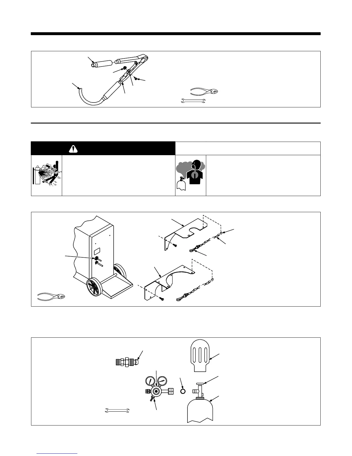
2-2. Installing Gas Supply
WARNING
CYLINDERS can explode if damaged.
• Keep cylinders away from welding and other
electrical circuits.
• Never touch cylinder with welding electrode.
• Always secure cylinder to running gear, wall, or
other stationary support.
BUILDUP OF SHIELDING GAS can harm
health or kill.
• Shut off shielding gas supply when not in use.
warn4.1 9/91
A . Installing Safety Chain
1 Cylinder Bracket As Shipped
2 S-Hook
Crimp between small hole in
bracket and chain.
3 Chain
4 Snap
Crimp onto open end of chain.
5 Cylinder Bracket For Large
Gas Cylinder
6 Gas Fitting
ST-160 791
1
2
3
Tools Needed:
4
5
6
Figure 2-2. Installing Safety Chain
B . Installing Regulator/Flow Gauge
Obtain gas cylinder and chain to
running gear, wall, or other station-
ary support.
1 Cap
2 Cylinder Valve
Remove cap, stand to side of valve,
and open valve slightly. Gas flow
blows dust and dirt from valve.
Close valve.
3 Cylinder (CO
2
shown)
4CO
2
O-Ring
ssb3.1* 12/92 – ST-154 583 / ST-154 623 / Ref. ST- 800 746
Tools Needed:
1-1/8, 5/8 in
5
6
2
3
4
1
5 Regulator/Flow Gauge
Install so face is vertical.
6 Gas Hose Connection
Install gas hose between flow
Gauge and welding power source.
Flow rate is set to 20 cfh (cubic feet
per hour).
7 Adapter
Install adapter between regulator/
flow gauge and cylinder when using
argon or mixed shielding gas.
7
Figure 2-3. Installing Supplied Regulator/Flow Gauge