S-0092-G
OM-154 500 Page 3
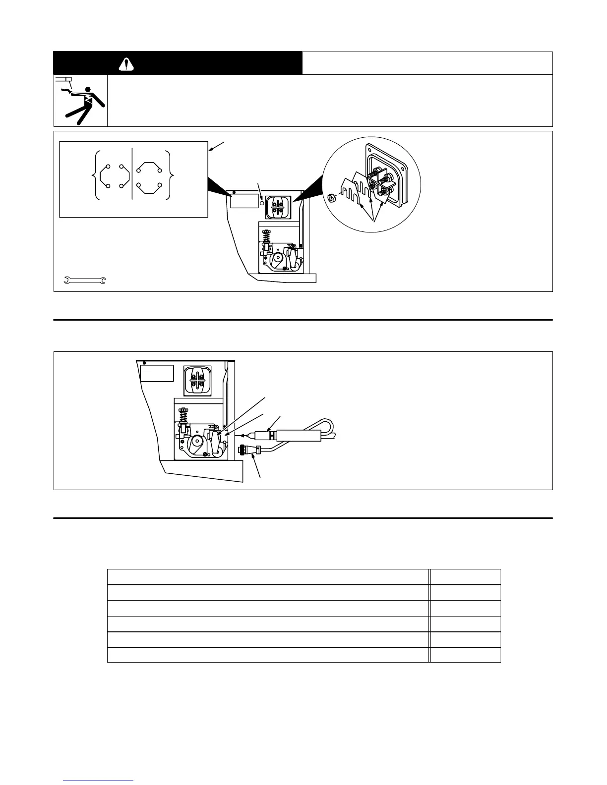
2-3. Gun Polarity For Wire Type
WARNING
ELECTRIC SHOCK can kill.
• Do not touch live electrical parts.
• Turn Off welding power source, and disconnect input power before inspecting or installing.
swarn1.1 2/93
1 Polarity Changeover Label
2 Polarity Jumper Links
Always read and follow wire man-
ufacturer’s recommended polarity.
There are two jumper links (1 set)
across each set of terminals. Be
sure to move each set of links when
changing polarity.
3 Pilot Light (See Section 4-1)
Close door.
Ref. ST-149 631-C
Tools Needed:
3/8 in
STRAIGHT
POLARITY
DCEN
REVERSE
POLARITY
DCEP
GUN POLARITY CHANGEOVER
For Flux
Cored Wires
(FCAW
Process)
For Solid
Steel Or
Wires
(GMAW)
S-116 599-C
Aluminum
Process)
2
3
1
Figure 2-4. Gun Polarity Connections
2-4. Installing Welding Gun
1 Gun Securing Knob
2 Drive Assembly
3 Gun End
Loosen securing knob. Insert end
through front panel opening until it
bottoms against drive assembly.
Tighten knob.
4 Gun Trigger Plug
Insert into receptacle and tighten
threaded collar.
Close door.
Ref. ST-149 629-B
2
4
1
3
Figure 2-5. Gun Connections
2-5. Connecting Input Power
Table 2-1. Electrical Service Requirements*
Input Voltage
230
Input Amperes At Rated Output
20
Recommended Standard Fuse Or Circuit Breaker Rating In Amperes
1
30
Input Conductor Size In AWG/Kcmil
2
14
Max Input Conductor Length In Feet (Meters)
3
65 (20)
Grounding Conductor Size In AWG/Kcmil
4
14
*
These values are calculated from the 1993 edition of the National Electrical Code (NEC).
1 Recommended fuse or circuit breaker size is that closest to 150% of rated input amperage of the welding power
source. Article 630-12(a) of NEC allows fuse or circuit breaker sizing up to 200% of rated input amperage.
2 Input conductor size is for insulated copper wire with 75°C rating with not more than three single current-carrying
conductors in a cable or raceway (Table 310-16 of NEC).
3 Maximum length is to prevent more than a 3% voltage drop between service entrance and input terminals of the
welding power source (Articles 210-19(a) and 215-2(b) of NEC).
4 The grounding conductor shall be colored or identified as specified in the NEC. Grounding conductor size for copper
wire is not required to be larger than input conductor (Article 250-95 of NEC).