OM-154 500 Page 4
WARNING
ELECTRIC SHOCK can kill.
• Do not touch live electrical parts.
• Turn Off welding power source, and disconnect input power before inspecting or installing.
• Have only qualified electrician install unit.
• Installation must meet National Electrical Code and all other codes.
swarn3.1* 10/91
ssb2.2* 3/92A – ST-149 630-B
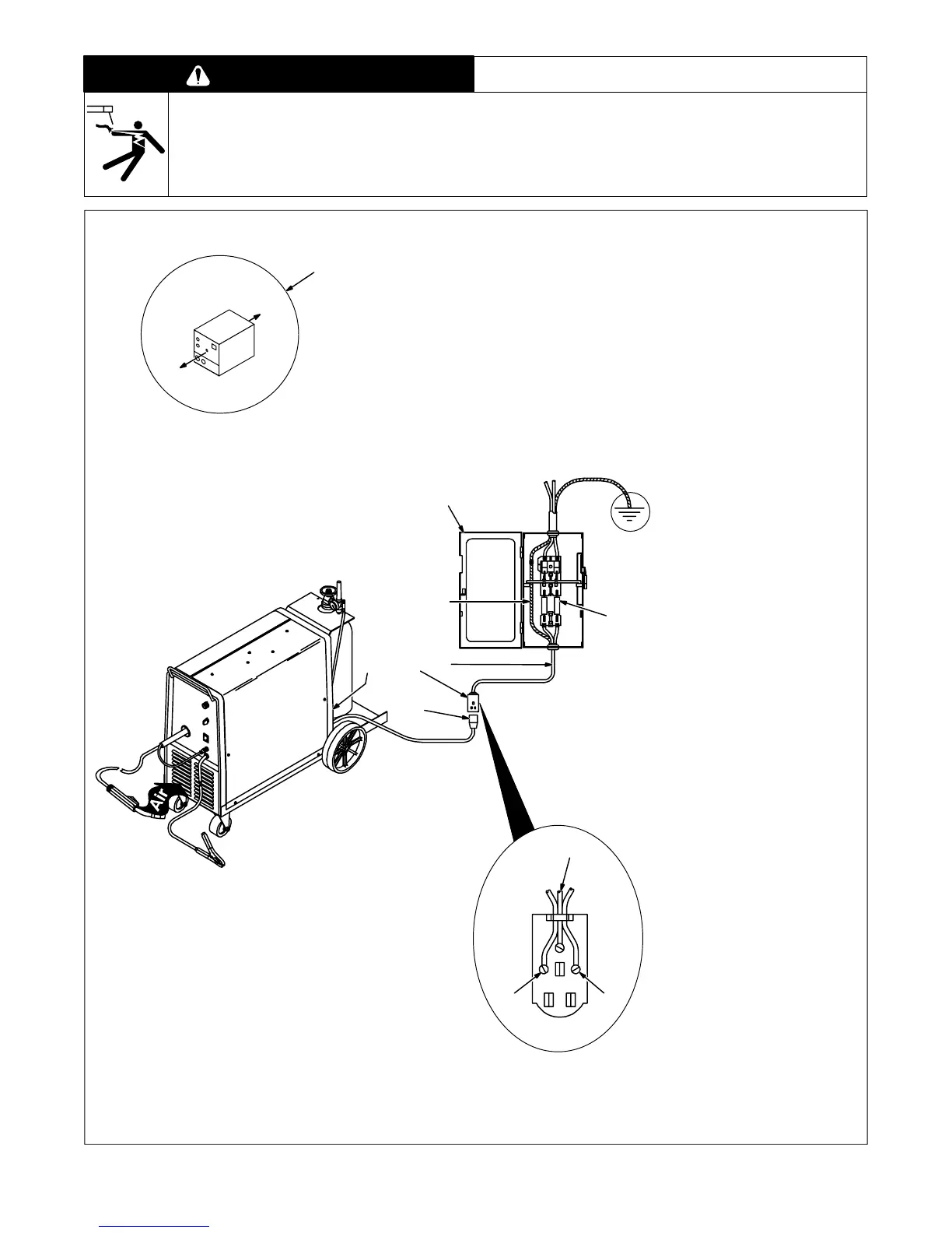
Front
Rear
4
4
5
1
8
3
7
Have only qualified persons make
this installation.
1 18 in (457 mm) Open Space
At Front And Rear For Good
Airflow
2 Rating Label
Supply correct input power.
3 230 Volts AC Wall Receptacle
4 Input Conductors
5 Grounding Conductor
Select size and length using
Table 2-1. Conductor rating must
comply with national, state, and lo-
cal electrical codes.
Install and connect input conduc-
tors and grounding conductor in
conduit or equivalent between wall
receptacle and deenergized line
disconnect device. Be sure ground-
ing conductor goes to an earth
ground.
6 Line Disconnect Device Of
Proper Rating
Obtain and install switch and wall
receptacle.
7 Overcurrent Protection
Select type and size using
Table 2-1. Install into deenergized
line disconnect device (fused dis-
connect switch shown).
8 Input Power Plug
Turn Off unit Power switch, and
connect plug to wall receptacle.
24
5
6
Figure 2-6. Location And Input Power Connections