NOTE: Before proceeding to check and adjust the wing balance, ensure the header
oat is set. Refer to Step 3: Seng Header Float for instrucons.
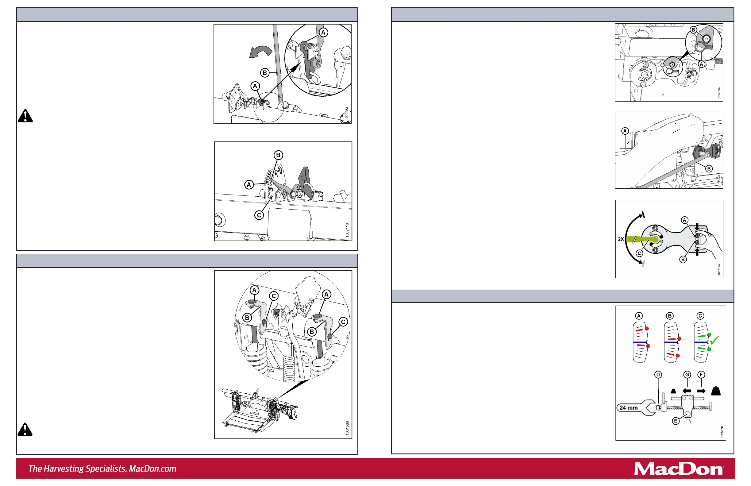
a. Aach ex checker cable (A) to ex checker cable lock (B).
NOTE: Images shown are from the le side.
b. On the side that you are adjusng, move spring handle (A) to the lower (UNLOCK)
posion. Keep the opposite wing locked. You should hear the lock disengage. If
not, use mul-tool (B) to rotate the mechanism so that the lock disengages.
c. On both sides of the oat module, place the header oat locks (shown in
Figure 3) in the locked posion.
d. On the ex checker plate, pinch indicators (A) and (B) together with your ngers.
e. Use mul-tool (C) to rotate the ex checker plate up unl the pin reaches the end
of slot. Lower indicator (B) will move down to give the rst reading.
f. Use mul-tool (C) to rotate the ex checker plate down unl the pin reaches the
end of the slot. Upper indicator (A) will move up to give the second reading.
g. Refer to Figure 10 and interpret the indicator posions as follows:
• Condion A – the wing is too light; make the wing heavier.
• Condion B – the wing is too heavy; make the wing lighter. a. Loosen bolts (C), and rotate spring locks (B).
• To decrease header weight, turn both adjustment bolts (A) equally
clockwise (decreasing the value on the FSI).
• To increase header weight, turn both adjustment bolts (A) equally
counterclockwise (increasing the value on the FSI).
NOTE: Ensure the FSI values are equal on both sides.
b. Aer adjustment, li the end of the header by hand and recheck the
FSI reading.
NOTE: If an adequate header oat cannot be achieved using all the
available adjustments, an oponal heavy duty spring is available. See
your MacDon Dealer or refer to the parts catalog for ordering
informaon.
c. Once the oat adjustment is complete, lock adjustment bolts (A) with
spring locks (B). Ensure that bolt heads (A) are engaged and ghten
bolts (C) to secure the spring locks.
d. Use the combine to fully lower the header. The le and right oat
seng levers will return to their original posions.
WARNING
Do NOT use the mul-tool to release the oat seng lever. Using
the mul-tool to release the oat seng lever can result in injury.
Step 3: Seng Header Float
a. On the le side of the header, li oat seng lever (A) by hand to
remove slack.
b. Fully engage the at end of mul-tool (B) on the oat seng lever.
The mul-tool should be angled toward the front of the oat module.
c. Pull mul-tool (B) toward the back of the oat module unl lever (A) is
locked in place and will not return to its original posion.
d. Move the header up and down by hand several mes to reduce the
eect of fricon.
e. Remove the mul-tool and repeat on the opposite side.
WARNING
Once the oat seng lever has been set, remove the mul-tool
from the lever IMMEDIATELY. If the lever falls to its starng
posion while the mul-tool is engaged with it, injury can occur.
f. On the le side of the oat module, inspect smaller oat seng
indicator (FSI) (A). Arm (B) on the FSI should point to the number 2.
• If the FSI points to a value higher than 2, the header is too heavy.
• If the FSI points to a value lower than 2, the header is too light.
NOTE: The larger numbers (C) indicate the oat height while operang
the header in the eld.
NOTE: If necessary, adjust the oat values to suit crop and eld
condions. For more informaon, refer to the header operator’s
manual.
Step 2: Checking Header Float
Figure 5: Checking Float – Le Side Shown, View from Rear
Figure 4: Checking Float – Le Side Shown, View from Rear
a. If the wing is too light (Condion A), make it heavier by turning adjuster bolt (D)
to move clevis (E) in direcon (F).
b. If the wing is too heavy (Condion B), make it lighter by turning adjuster bolt (D)
to move clevis (E) in direcon (G).
c. Recheck the wing balance. Adjust as required unl the wing is balanced
(Condion C).
d. Move the spring handle to the upper (LOCK) posion.
e. If the lock does not engage, move the wing up and down with the mul-tool unl
it locks.
f. Detach the ex checker cable from the ex checker lock.
g. Repeat on the other side.
h. Return the mul-tool to its storage locaon, and reinstall the linkage cover.
Step 4: Checking Wing Balance
Step 5: Adjusng Wing Balance
Figure 8: Wing Balance Linkage
Figure 9: Wing Balance Adjustment
Figure 6: Float Adjustment Bolts – Le Side Shown
Figure 10: Wing Balance Adjustment
Figure 7: Flex Checker Cable

 Loading...


