EFX Board Modification Instructions:
Models affected:
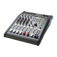
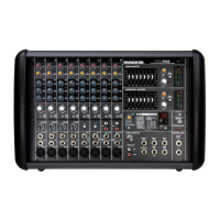
All PPM series powered mixers: 406M, 408M, 408S, 808M and 808S
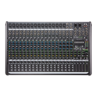
All CFX series compact effects mixers: CFX•12, CFX•16 and CFX•20
EFX pin1 modification SSE May 2000
EFXmod.pdf, page 1 of 2
Verify the following symptom on any of these units in for repair:
Symptom:
While program material is playing, if the EFX BYPASS switch
is depressed and a delay function is selected, as soon as the
EFX BYPASS is unselected, the program material that was last
recorded in the delay line is played at the outputs. In other
words, the EFX BYPASS switch acts like a sample and hold when
a delay function is selected.
Solution: Cut Pin 1 of the EFX board’s ribbon cable.
Safety Warning:
Caution! These instructions are for use by qualified personnel
only. To avoid electric shock, do not perform any servicing
unless you are qualified to do so. Refer all service and modifying
to qualified personnel.
Tools Required:
Sharp pair of electrical cutters, Phillips screwdriver, safety glasses.
Powered Mixer repair
In order to perform this on the Powered Mixer series, the front panel must be removed.
1/ Remove all cords- including the power cable and speaker outputs- from the mixer.
2/ Place the mixer on a dry, non-marring surface with the heat sink facing down.
3/ Remove the six screws securing the front panel of the mixer to the plastic enclosure. These are
located three per side on the far left and right edges of the front panel. Keep track of which
screws go where.
4/ Carefully disconnect the white block connector located on the right side of the front panel of the
mixer.
5/ Disconnect the green 16-gauge chassis ground wire located in the center of the bottom edge of
the mixer’s front panel.
6/ Remove the mixer front panel from the plastic chassis and place face down on a dry, non-marring
surface.
7/ Pull the ribbon cable off the EFX board and cut pin 1 as shown in the diagram on page 2. The cut
should be flush with the ribbon cable’s insulation, so there is no chance of any electrical contact.
8/ Replace the ribbon cable onto the EFX board, making sure that all pins are inserted correctly, and
there is no connection to pin 1.
9/ Reassemble the mixer and fully retest before returning it to your customer.
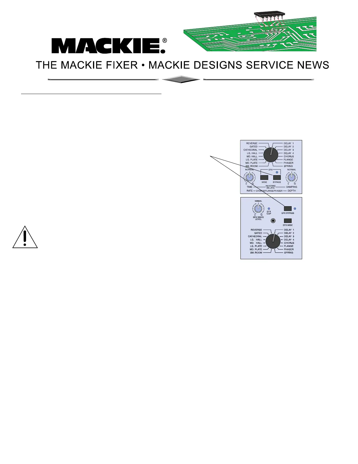
Front
panel EFX
controls for
CFX mixers
Front
panel EFX
controls for
PPM mixers
 Loading...