Page 4 of 20
Maintenance Procedures
Ensure that the fluid supply to the meter is dis-
connected, and the line pressure is released be-
fore disassembly, with the exception for repair or
maintenance to the LC Display or PCB where
there is no necessity to isolate the meter from flow.
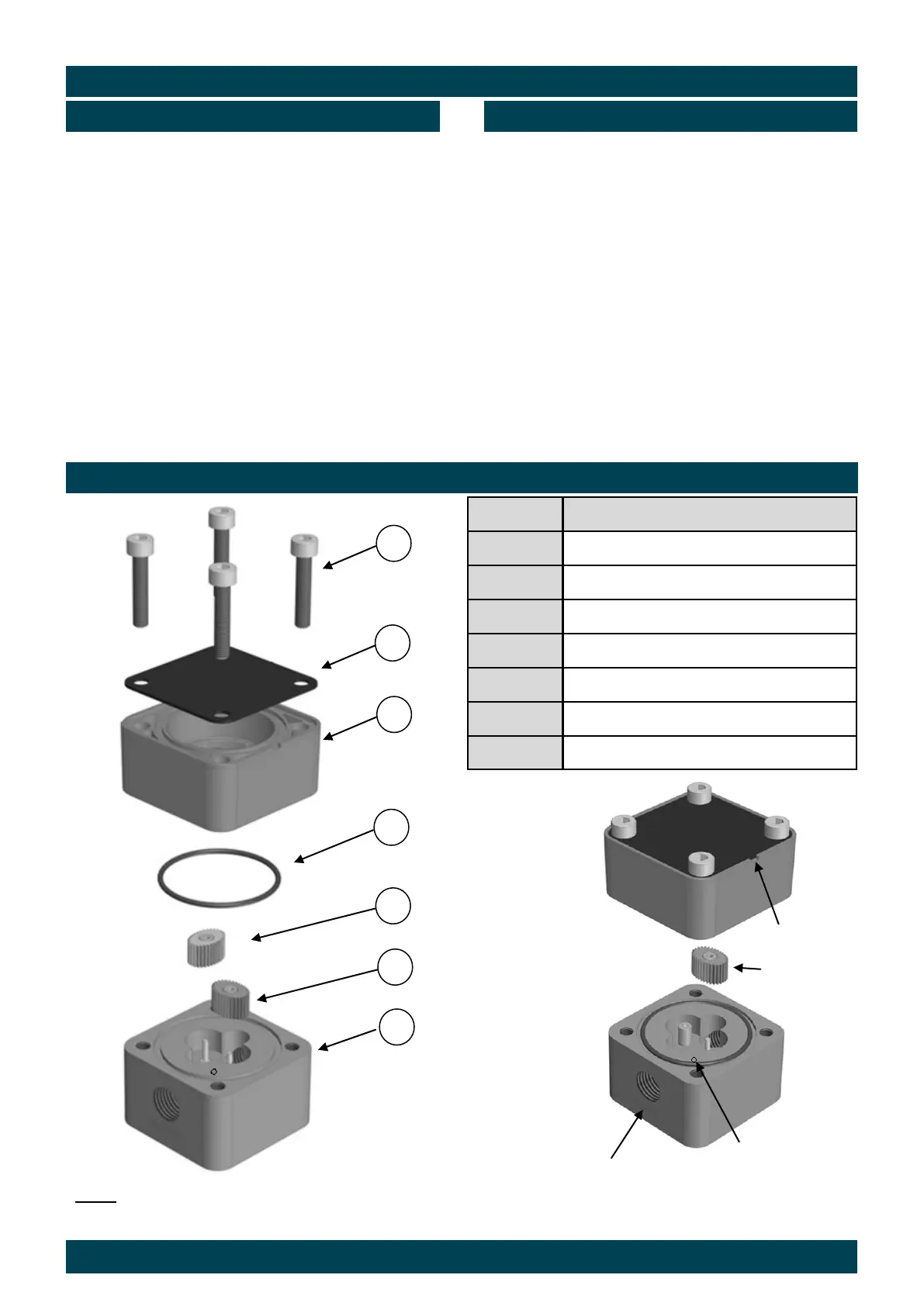
Refer to the below exploded parts diagram.
1. Loosen and remove 4 Phillips head or cap head
screws (Item 7).
2. Remove the meter cap (Item 5) and O-Ring (Item
4).
3. Remove the rotors (Item 2 & 3), note the position/
orientation of the rotor with the magnet(s) or grub
screws
4. Clean and Inspect all components, replace as
necessary, see page 12 & 13 for spare parts
listing.
1. Place the rotors (Item 2 & 3) on the shafts inside
the body at 90° to each other in the same way as
it was originally factory fitted. Rotate the rotors
by hand to ensure correct engagement.
2. Fit the O-Ring (Item 4) into the O-Ring groove in
the meter body (Item 1).
3. Fit the top cap assembly (Item 5), fit the legend
plate (Item 6) into correct orientation. Ensure all
the alignment marks are lined up with the mark
on the body.
4. Fit and tighten the 4 bolts/screws (1-3-2-4, Item 7
to the required torque. (See page 11 for details)
5. Check meter function using low air pressure.
Restore the fluid & reconnect the wiring as
detailed on pages 6-10.
Disassembly Reassembly
Item No Part Description
1 Meter Body
2 Active Rotor
3 Neutral Rotor
4 O-Ring
5 Meter Cap
6 Legend Plate
7 Meter Cap Screws
7
6
5
4
3
2
1
Exploded Diagram - Type M,F,S,CR
Cap Notch
Active Rotor
Port Inscription
Alignment Dimple
The Active Rotor, Alignment Dimple and Cap Notch must be aligned when assembling the flow-
meter. The ‘CR’ Range has a notch in the body not an alignment dimple. Magnet hole/grub screw
side must be facing the meter body.