ES FR
EN
IT
20
Madas Technical Manual - 9|9.4 - REV. 0 of 8
th
Feb 2019MTC10
5.0 CONFIGURATION
Here are some examples of the most common installations:
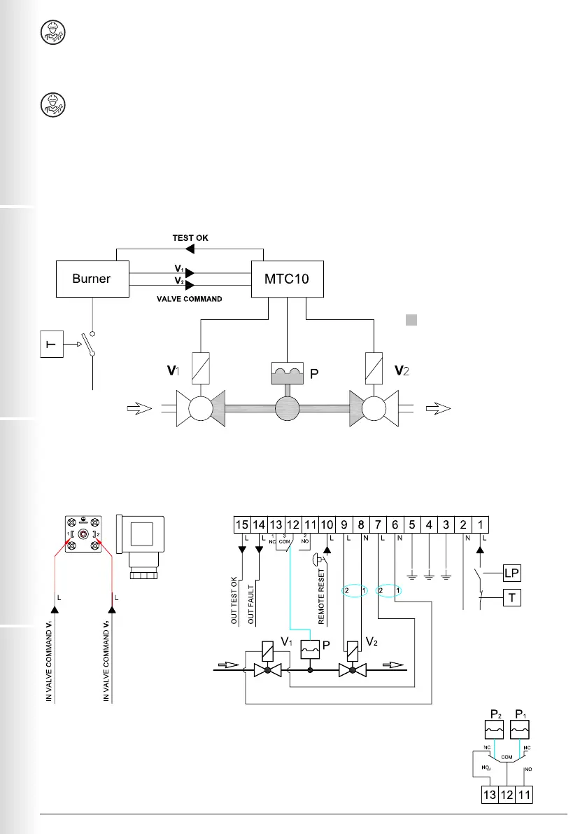
5.1 - STANDARD CONFIGURATION -STD-
The MTC10 controls valves V1 and V2.
The following checks are performed before starting the burner:
1. Leak test V1
2. Leak test V2
After the test, the device waits for the signal provided by the Burner Control. Once the signal is received, V1 and V2 on the
valve control connector are opened.
EXAMPLE 1
Valve Control Electrical connections
V1: NC safety solenoid valve
V2: NC work solenoid valve
P: Pressure switch
T: Thermostat
LP: Minimum pressure switch
: Test volume
P
1
: Low pressure switch
P
2
: High pressure switch