EasyManua.ls Logo

MADDALENA microCLIMA/SENSOSTAR 2+ MSH User Manual

MADDALENA microCLIMA/SENSOSTAR 2+ MSH
14 pages
To Next Page IconTo Next Page
Page #1 background imageLoading...
Page #1 background image
Doc. code 1080100090 Version: 2015_03_03 1
Installation and Operating Instructions
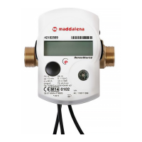
Thermal Energy Meter (Compact Heat Meter, Combined Heat/Cooling Energy Meter)
microCLIMA/SENSOSTAR®2/2+ MSH
Model MSH DE-07-MI004-PTB001 (MID heat)
Model QStar DE-08-MI004-PTB005 (MID heat)
1 Application and Function
Thermal energy meter designed for the measurement of the consumed thermal energy in a closed heating system
or heating / cooling system.
2 Contents of the Package
- Thermal energy meter consisting of a calculator, a flow sensor and two temperature sensors, connected
permanently
- Installation kit MSH-SStar, -VStar, -MStar, -AStar or QStar (depending on type)
- Depending on type of the flow sensor (label):
EAS identification EN14154 (IST)
EAS identification “EN14154”(TE1)
EAS identification “EN14154” (M60)
EAS identification “EN14154”(A1)
- Installation and Operating Instructions
3 General Information
- Valid standards for the application of heat meters: EN 1434, parts 1 6; the Measuring Instruments
Directive 2004/22/EC, Annexes I and MI-004, and the relevant national verification regulations.
- For the selection, installation, commissioning, monitoring and maintenance of the instrument observe the
standard EN 1434 part 6 as well as Annex 22 of the verification regulations (for Germany).
- National regulations for the consumption measurement of cooling must be observed.
- The technical regulations for electrical installations must be observed.
- This product fulfils the requirements of the European Council Directive on Electromagnetic Compatibility
(EMC Directive) 2004/108/EC.
- The identification plate of the instrument and the seals must not be removed or damaged otherwise the
guarantee and the approved application of the instrument are no longer valid!
- To achieve measurement stability of the meter it is necessary that the water quality meets the
requirements of the AGFW-recommendation FW-510 and the document VDI (Association of German
Engineers) VDI 2035.
- The heat meter left the factory in conformance with all applicable safety regulations. All maintenance and
repair work is to be carried out only by qualified and authorized technical personnel.
- The instrument must be stored and transported at temperatures above-freezing.
- Instruments with activated radio function are not allowed on air freight.
- The correct installation point in the system must be chosen: forward or return flow, as stated on the type
identification label.
- The temperature sensor cables and the cable between the calculator and flow sensor must not be kinked,
rolled up, lengthened or shortened.
- To clean the heat meter (only if necessary) use a slightly moist cloth.
- To protect against damage and dirt the heat meter should only be removed from the packaging directly
before installation.
- If more than one heat meter is installed in one unit, care must be taken to ensure that all the meters have
the same installation conditions.
- All specifications and instructions listed on the data sheet and in the Application Notes must be adhered
to.
Question and Answer IconNeed help?

Do you have a question about the MADDALENA microCLIMA/SENSOSTAR 2+ MSH and is the answer not in the manual?

MADDALENA microCLIMA/SENSOSTAR 2+ MSH Specifications

General IconGeneral
BrandMADDALENA
ModelmicroCLIMA/SENSOSTAR 2+ MSH
CategoryMeasuring Instruments
LanguageEnglish

Summary

General Information and Requirements

Operational Guidelines and Warnings

Covers seal integrity, water quality, maintenance, storage, cable handling, and packaging.

Flow Sensor Mounting Procedures

4.1 MSH-SStar (EAS) Installation

Details installation of MSH-SStar sensor in EAS connection piece, including checks and steps.

4.2 MSH-VStar (ASS) Installation

Details installation of MSH-VStar sensor in ASS connection piece, including checks and steps.

4.3 MSH-MStar (M60x1,5) Installation

Details installation of MSH-MStar sensor in M60x1,5 connection, including checks and steps.

4.4 MSH-AStar (EAT M77x1,5) Installation

Details installation of MSH-AStar sensor in EAT M77x1,5 connection, including checks and steps.

Correct Positioning for MSH-AStar

Advises checking directional arrows for correct flow positioning during MSH-AStar installation.

4.5 MSH-QStar Installation

Details installation of MSH-QStar sensor, including flushing, removal, preparation, and tightening.

Temperature Sensor Mounting

Direct Immersion for Small Pipes

Specifies direct immersion for sensors in pipes < DN25 and marking checks.

5.1 Direct Mounting in Ball Valve/T-piece

Guides on direct mounting, removing old sensors, O-ring placement, and insertion depth.

5.2.1 MSH-AStar Direct Mounting

Details direct mounting of MSH-AStar sensors, including safety and sealing.

Meter Start-up Procedure

Final Sealing and Verification

Final step to attach seals for tamper protection and verify meter readings.

Display Information

Display Overview and Navigation

Describes the LCD, data loops, and navigation using the push-button.

Technical Specifications

Approval and Sensor Data

Lists approval data, accuracy classes, and flow sensor specifications.

Interfaces and Options

Radio Interface Configuration and Activation

Covers factory clock settings, radio activation, installation mode, and read-out software.

9.4.3 Radio Activation Methods

Explains manual and software-based activation of the radio interface.

Hint Flags

Handling Hint Flags

Advises on actions for most hint flags, suggesting exchange for specific errors.

Hint/Error Details

Error Codes, Effects, and Causes

Details specific hint/error codes, their effects on operation, and possible causes.

Related product manuals