507390-03 Issue 2217 Page 5 of 12
permanent lter, shake the lter to remove excess dirt
and/or use a vacuum cleaner. Wash the lter in soap or
detergent water and re-install after lter is dry.
The lter supplied need not be oiled after washing.
If an installation is made in which it is more desirable to
mount the lter exterior to the unit, in the return duct work
or otherwise, the permanent lter supplied can be used
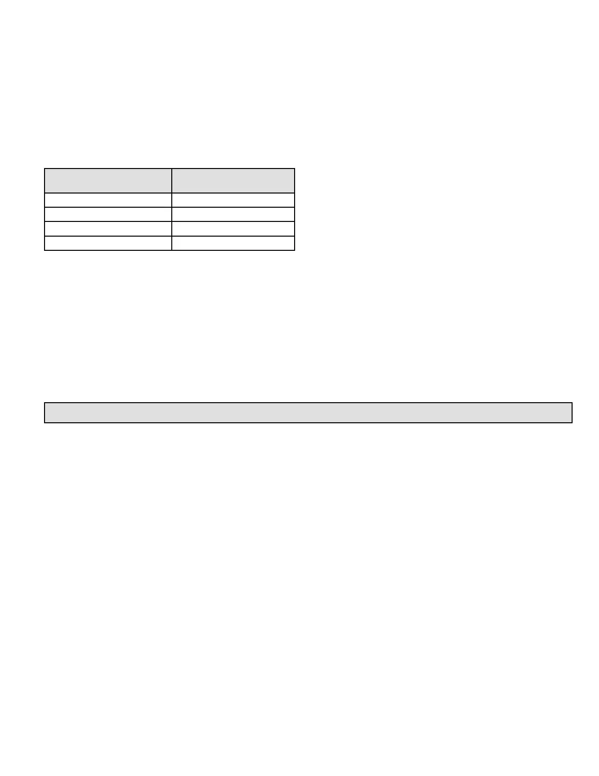
or a disposable lter may be used. If a disposable lter is
used, the minimum area required is as shown in Table 1.
Cooling Chassis Model
Number
Filter Area
(sq. in.)
EWC*12 300
EWC*18 480
EWC*24 480
EWC*30 480
Table 1. Minimum Required Surface Area for
Disposable Filters
Operation
Operation of this unit is automatic and will provide heating
or cooling depending on the setting of the thermostat.
Heating
1. Turn on the main power supply.
2. Set the thermostat system switch to “HEAT”.
3. Set the thermostat heating scale to the temperature
desired.
Cooling
1. Set the thermostat system to “COOL”.
2. Set the thermostat cooling scale to the temperature
desired.
Blower Operation
Continuous operation of the air handling blower will be
obtained if the thermostat fan switch is set to “ON”.
With the thermostat switch set to “AUTO”, the air handling
blower will cycle corresponding with the thermostat cycling.
Ductwork
Provide ductwork suciently large to handle the larger
of the air volumes for heating or cooling provided by this
model.
Connect supply duct to top of unit using canvas connection
or other exible connection to prevent noise transmission
into the duct system.
To connect the return duct to the unit, use a straight piece
of duct 22” wide by 6” deep.
Insert the duct into the opening in the bottom of the unit
and ange the duct over the existing anges around the
opening inside the unit. Make sure that all sides of the duct
are anged over to permit removal of the cooling chassis if
required. Use a exible connection to attach the remainder
of the return ductwork.
Adjustments
No adjustments are required or should be attempted
regarding any of the components of the cooling chassis
and electric heating section.
The unit should be checked to see that none of the wiring is
loose or missing. The plug-in electrical connector between
the cooling chassis and the main control compartment
should be checked to make sure that the plug is rmly
seated and none of the wires are loose.
To Shut Down Unit
For temporary or short periods of shutdown, set the
thermostat system switch to “OFF”. For a prolonged period
of shutdown, set the thermostat system switch to “OFF”
and turn o the electrical power supply.
Blower
The unit contains a direct drive, multi-speed blower motor.
The proper speed has been set at the factory. Refer to the
wiring diagram on the unit for proper wiring connections.
 Loading...