507388-03 Issue 2110 Page 11 of 19
Start-Up
For Your Safety Read Before Lighting
If you do not follow these instructions exactly, a re
or explosion may result causing property damage,
personal injury, or loss of life.
WARNING
This furnace is equipped with a direct ignition control.
Do not attempt to manually light the burners.
CAUTION
To Light Main Burners
1. Turn o electrical power to unit.
2. Turn the thermostat to lowest setting.
3. Move the gas valve ON/OFF switch to the “ON”
position (Figure 7).
4. Turn on electrical power to the unit.
5. Set the room thermostat to the desired temperature.
(If the thermostat “set” temperature is above room
temperature after the pre-purge time expires, main
burners will light.)
To Shut Down Main Burners
1. Turn o electrical power to unit.
2. Move the ON/OFF switch to the “OFF” position (Figure
7).
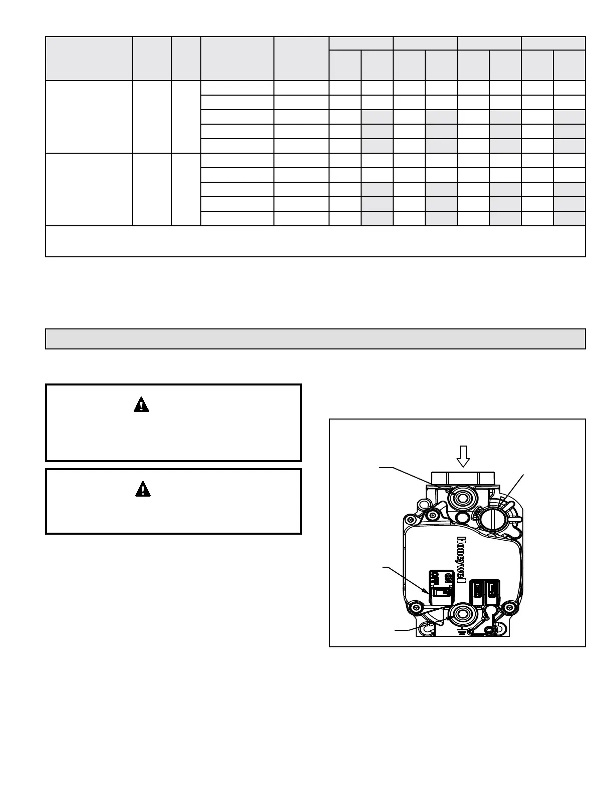
Figure 7. Gas Valve
Gas Inlet
ON/OFF
Switch
Gas Inlet
Pressure Test
Tap
Regulator Adjustment
Screw
(Under Cap)
Gas Manifold
Pressure Test
Tap
Model
Rise
Range
(°F)
Mid
Rise
(°F)
Indoor Blower
Speed
Unit Voltage
(V)
0.1“ w.c. 0.2“ w.c. 0.3“ w.c. 0.4“ w.c.
SCFM
Temp
Rise
(°F)
SCFM
Temp
Rise
(°F)
SCFM
Temp
Rise
(°F)
SCFM
Temp
Rise
(°F)
HWC8N4812P30A 30-60 45
TAP 1 (HEAT) *
208 or 230 780 46 755 47 730 49 710 50
TAP 2 (HEAT)
208 or 230 900 40 875 41 855 42 835 43
TAP 3 (COOL) †
208 or 230 530 510 490 465
TAP 4 (COOL)
208 or 230 570 545 530 505
TAP 5 (COOL) †
208 or 230 950 920 900 885
HWC8N6012P30A 45 - 75 60
TAP 1 (HEAT)
208 or 230 780 57 755 59 730 61 710 63
TAP 2 (HEAT) *
208 or 230 900 49 875 51 855 52 835 53
TAP 3 (COOL) †
208 or 230 530 510 490 465
TAP 4 (COOL)
208 or 230 570 545 530 505
TAP 5 (COOL) †
208 or 230 950 920 900 885
N/A: Do not operate unit in heating mode using this blower speed at this external static pressure outside of the proper temperature rise range.
NOTE: HWC**30A models shipped with Low and High stage Cooling taps connected for use of the two-stage system.
* As shipped speed for Heating operation
† As shipped speed for Cooling operation
Table 2. Supply Airow Performance (SCFM) as a Function of External Static Pressure