17
9
16
15
14
13
12
2
2
3
4
5
6
7
8
9
10
11
1
4
76
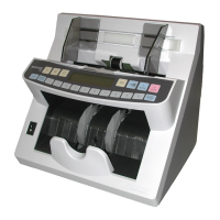
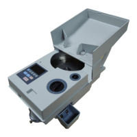
Appearance
Figure 1
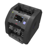
Figure 2
1 Screw to
adjust a gap between
hopper's rollers.
2 Banknote guides.
3 Hopper.
4 Locks providing
access to
mechanism.
5 Control panel.
6 Reject pocket.
7 Stacker.
8 Stacker wheels.
9 Carrying handles.
10 Upper part.
11 Base.
12 Power switch.
13 Fuse.
14 Power connector.
15 Connector for an e xternal printer
or a video surveillance
device.
16 USB port for PC connection.
17 Socket for external display.
External Sensors, path sensors and pocket switch
To open the path, press simultaneously the fixing an upper part (see locks
Figure 1, item 4), and then, holding the the case, pull the upper part hollows of
of the (see Figure 2, item 10) up to the stop. To close the path, push counter
the upper part up to a click.
Figure 5, Figure 6, and Figure 7 show the external sensors, the path
sensors and the .pocket switch
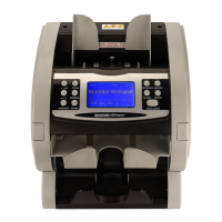
Control panel
Figure 3
1 The softkeys for the
start and user
selection.
2 Touch screen display.
1 Hopper sensors
2 Reject pocket sensor
3 Stacker sensors
11 2
4 The UV transmission sensors/the
input path sensors
5 Contact image sensor (CIS)
Figure 4
Figure 5
5
44
2
1
3
MAGNER PRB VALUE COUNTERMAGNER PRB VALUE COUNTER